Multi-phase voltage converting device, vehicle and control method of multi-phase voltage converting device

a voltage conversion device and multi-phase technology, applied in the direction of hydrogen technology, battery/fuel cell control arrangement, transportation and packaging, etc., can solve the problem of large output voltage ripple of multi-phase voltage converting device, inability to change the control period of the unit, and inability to keep the same phase difference at the same time. problem, to achieve the effect of suppressing the output voltage ripple of the voltage converting devi

Active Publication Date: 2010-01-07
TOYOTA JIDOSHA KK
View PDF9 Cites 9 Cited by
  • Summary
  • Abstract
  • Description
  • Claims
  • Application Information

AI Technical Summary

Benefits of technology

[0026]According to the invention, the output voltage ripple of the voltage converting device can be suppressed even when changing of the carrier takes place.

Problems solved by technology

However, each phase control unit cannot change the control period at some midpoint in the control period.
Thus, such a result occurs that the same phase difference cannot be kept between the phases at the time of carrier switching.
Consequently, the output voltage ripple of the multi-phase voltage converting device may be large.

Method used


Image

  • Multi-phase voltage converting device, vehicle and control method of multi-phase voltage converting device
  • Multi-phase voltage converting device, vehicle and control method of multi-phase voltage converting device
  • Multi-phase voltage converting device, vehicle and control method of multi-phase voltage converting device

Examples


Embodiment Construction

[0035]Embodiments of the invention will be described below with reference to the drawings. In the following description, the same or corresponding portions bear the same reference numbers, and description thereof is not repeated.

[0036]FIG. 1 is a circuit diagram showing a structure of a vehicle 100 according to the embodiment. Vehicle 100 is a fuel-cell electric vehicle that is an example of a vehicle equipped with en electric motor.

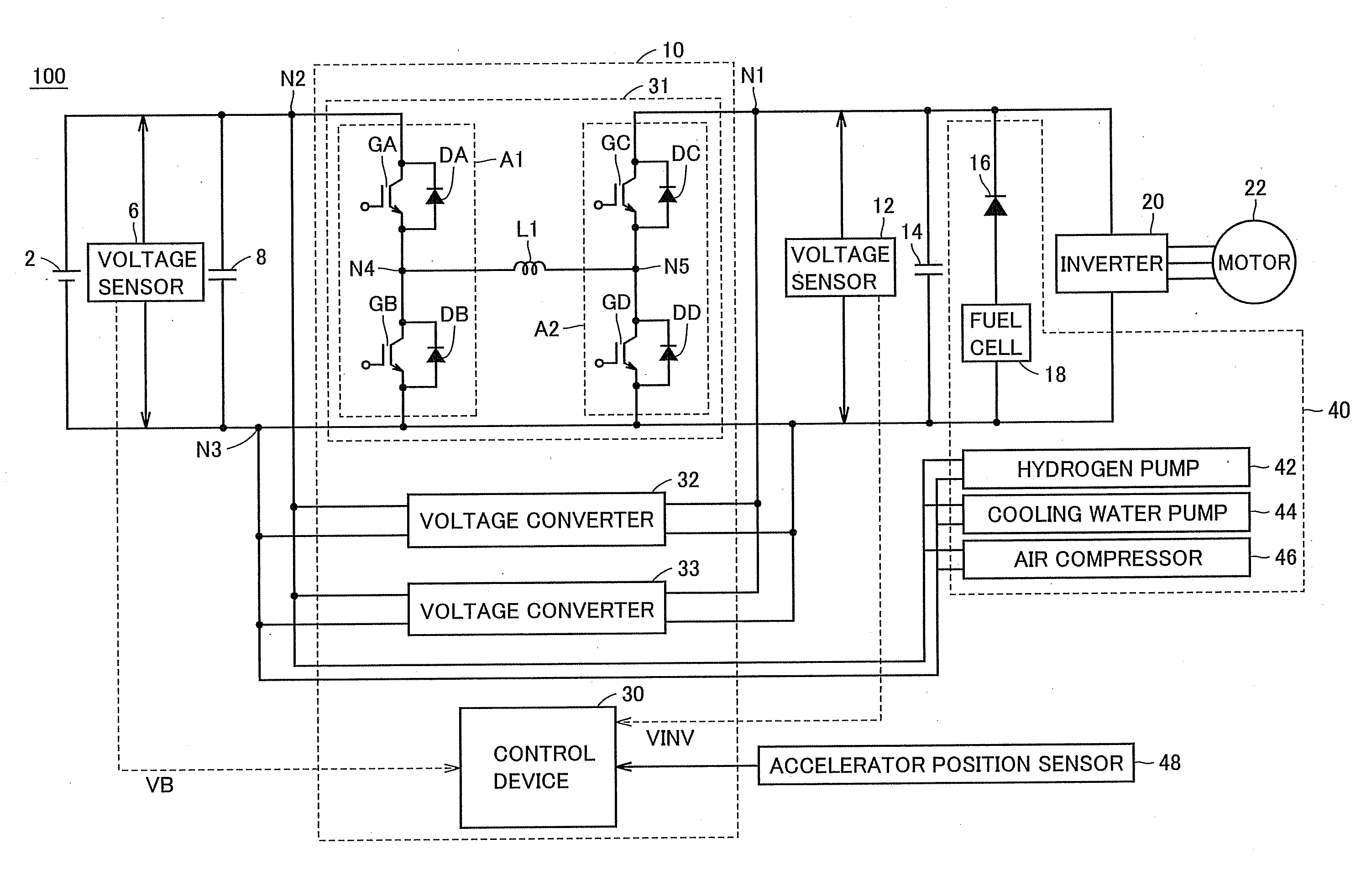
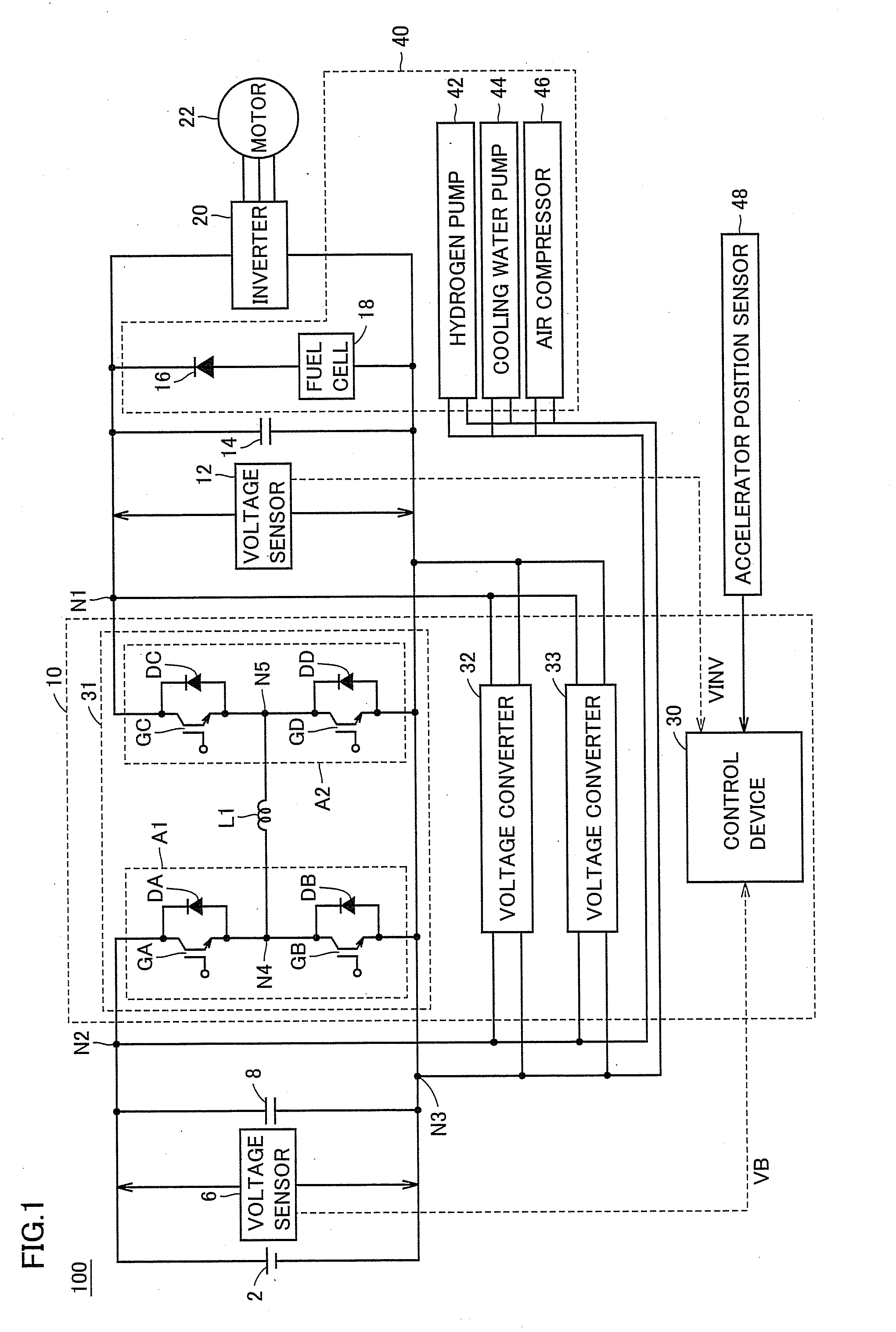
[0037]Referring to FIG. 1, vehicle 100 includes a battery 2 connected between nodes N2 and N3, a smoothing capacitor 8 connected between nodes N2 and N3, and a multi-phase voltage converting device 10 that is connected between nodes N2 and N3, and performs voltage conversion mutually between a voltage VB of the battery and a voltage VINV of an inverter.

[0038]Vehicle 100 further includes a smoothing capacitor 14 connected between nodes N1 and N3, an inverter 20 connected between nodes N1 and N3, a motor 22 driven by inverter 20, and a fuel cell system 40....


PUM


Abstract

A multi-phase voltage converting device includes voltage converters each performing voltage conversion based on a control period selected from among a plurality of predetermined control periods, and a control device indicating the control period to the voltage converters. The control device updates the control period of voltage converters in a predetermined period related commonly to the plurality of control periods. The update period is a least common multiple of the plurality of control periods. The plurality of voltage converters are n in number, and the control device successively updates the control periods for the plurality of voltage converters with a time difference equal to 1 / n of the update period. Thereby, the multi-phase voltage converting device suppressing output voltage ripples can be provided.

Description

TECHNICAL FIELD[0001]The present invention relates to a multi-phase voltage converting device, a vehicle with the same and a control method of the multi-phase voltage converting device.BACKGROUND ART[0002]Japanese Patent Laying-Open No. 2004-357388 has disclosed a step-up / down converter of a multi-phase multiplex type that has a step-up function and a step-down function. This step-up / down converter is controlled such that currents having phases shifted from each other are passed for respective phases of the converter.[0003]FIG. 7 is a waveform diagram for illustrating a multi-phase (three-phase) converter.[0004]Referring to FIG. 7, for a single phase, a battery current that is not smoothed with a control period of 100 μs has a large amplitude, and a large ripple current flows even after the smoothing. Conversely, when a three-phase converter operates with the same control period, PWM signals of respective phases may have a phase difference of 120 degrees therebetween, and thereby a ...

Claims


Application Information

Patent Timeline
Patent Type & Authority Applications(United States)
IPC IPC(8): H02M5/45
CPCB60L11/1881B60L11/1892Y02T90/34H02M3/1584H02M3/1582B60L58/30B60L58/33Y02T90/40H02M3/155
Inventor HASEGAWA, TAKAHIKOMANABE, KOTA
Owner TOYOTA JIDOSHA KK
Why Eureka
Try Eureka