Microwave trigger metal-enhanced chemiluminescence (mt mec) and spatial and temporal control of same

a microwave trigger and chemiluminescence technology, applied in the field of bioassays, can solve the problems of limited chemiluminescent based detection, inability and inability to find comparable systems to overcome the shortcomings of using chemiluminescent based reaction detection methods. , to achieve the effect of enhancing electric fields, increasing reaction rates, and increasing intensity

Active Publication Date: 2010-01-07
UNIV OF MARYLAND BALTIMORE COUNTY
View PDF20 Cites 15 Cited by
  • Summary
  • Abstract
  • Description
  • Claims
  • Application Information

AI Technical Summary

Benefits of technology

[0021]This embodiment can be enhanced by placement of metallic structures having a shape with an apex area and positioning such apex areas adjacent to each other and creating a reactive zone therebetween. The reactive zone therebetween is prepare for placement of the immobilized capture molecule complementary to a target molecules. Further, the apex area and reactive zone can be exposed to microwave energy in an amount to increase the reaction rate in biological and clinical assay; increases intensity of emissions from the chemiluminescence reaction in both biosensing and chemical sensing technologies; enhance electric fields by focusing electromagnetic fields in the reactive zone and / increase Brownian motion in molecules contained within the reactive zone.
[0022]The metallic structures when fabricated into geometric shapes comprising an apex area for forming a reactive zone can be positioned on assay system with multiple wells wherein the reactive zone includes the wells and exposure to microwave energy enhances the reactions therein.

Problems solved by technology

However, chemiluminescent based detection is currently limited by the availability of chemiluminescent probes, which is not a factor governing fluorescence based detection [9].
Both fluorescence and chemiluminescence based technologies do however suffer from an inherent need for increased sensitivity / detection limits [8, 9].
However, to date no one has found any comparable systems to overcome the shortcomings of using chemiluminescent based reaction detection methods.

Method used


Image

  • Microwave trigger metal-enhanced chemiluminescence (mt mec) and spatial and temporal control of same
  • Microwave trigger metal-enhanced chemiluminescence (mt mec) and spatial and temporal control of same
  • Microwave trigger metal-enhanced chemiluminescence (mt mec) and spatial and temporal control of same

Examples


examples

1. Radiating Plasmons Generated from Chemically Induced Electronic Excited States

1.1 Materials

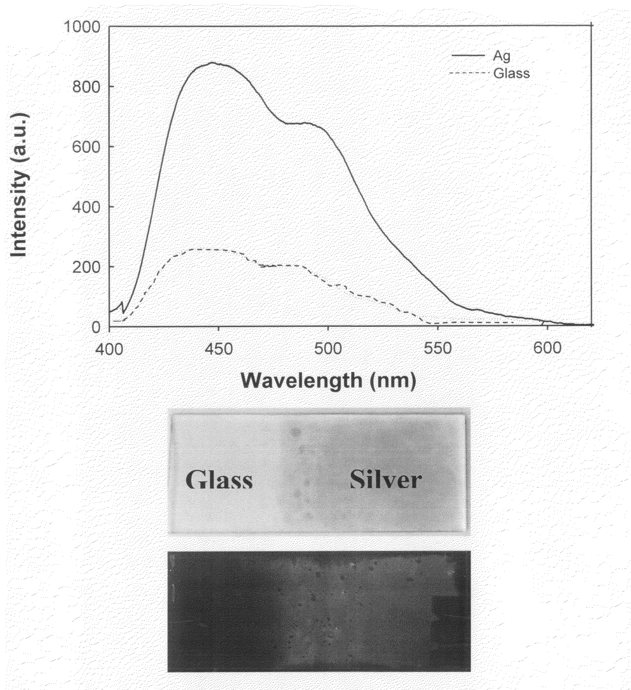
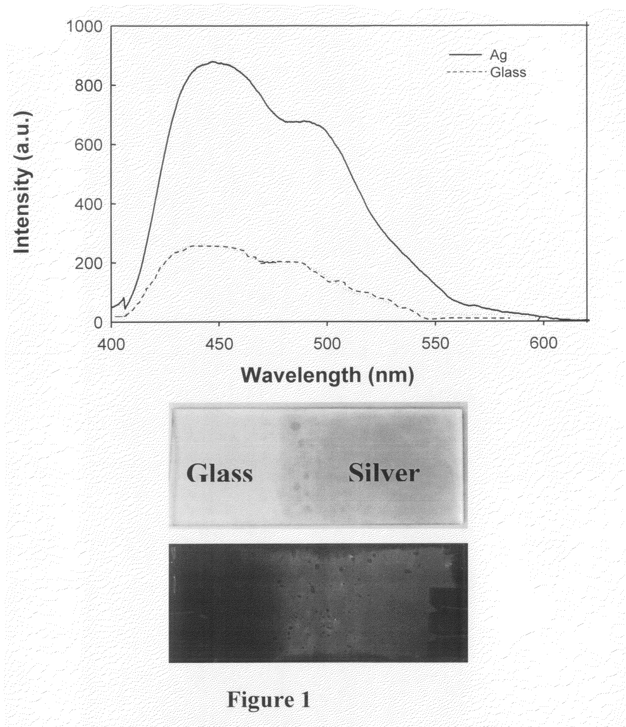
[0150]Silver nitrate (99.9%), sodium hydroxide (99.996%), ammonium hydroxide (30%), trisodium citrate, D-glucose and premium quality APS-coated glass slides (75×25 mm) were obtained from Sigma-Aldrich (St. Loius, Mo.). The blue-glow chemiluminescence sticks used were the “Color Bright” light sticks, obtained from Omniglow (West Springfield, Mass.).

1.2 Chemiluminescence

[0151]The chemiluminescent materials used in this study were obtained from commercial light glow sticks. These glow sticks contain the necessary reacting chemicals encapsulated within a plastic tube. The plastic tube contains a phenyl oxalate ester and a fluorescent probe, where the choice of dye simply determines the color of the luminescence [9]. For the examples set forth herein, this choice is arbitrary as long as the luminophore emits in the visible spectral region, consistent with previous reports [10-13]. Inside the pla...


PUM

PropertyMeasurementUnit
poweraaaaaaaaaa
diameteraaaaaaaaaa
diameteraaaaaaaaaa

Abstract

The present invention relates to a method of imaging structures and features using plasmonic emissions from metallic surfaces caused by chemiluminescence based chemical and biological reactions wherein imaging of the reactions is enhanced by the use of microwave energy and further enhanced by using metallic geometric structures for spatially and temporally controlling the biological and chemical reactions.

Description

CROSS REFERENCE TO RELATED APPLICATIONS[0001]The present application claims priority to U.S. Provisional Patent Application No. 60 / 902,982 filed on Feb. 23, 2007 and PCT Application No. PCT / US2007 / 062041 filed on Apr. 13, 2007 which in turn claims priority to U.S. Provisional Patent Application No. 60 / 773,037 filed on Apr. 13, 2006, the contents of all applications are hereby incorporated by reference herein.BACKGROUND OF THE INVENTION[0002]1. Field of the Invention[0003]The present invention relates to bioassays, and more particularly, to the use of metallized surfaces to enhance intensity of chemiluminescence species or reactions in assays thereby increasing sensitivity and detectability of same.[0004]2. Background of the Related Art[0005]The use of light-producing chemical reactions for quantitative detection in biotechnology is increasing [1-7], especially with regard to chemiluminescence based ligand-binding assays [1-7]. The attractiveness of chemiluminescence as an analytical...

Claims


Application Information

Patent Timeline
Patent Type & Authority Applications(United States)
IPC IPC(8): G01N33/53G01N21/76G01N33/00G01N33/50G01N33/48G01N33/03C12M1/34
CPCG01N21/76G01N33/54306G01N33/5438G01N33/553G01N21/763Y10T436/147777Y10T436/144444Y10T436/201666Y10T436/145555Y10T436/23Y10T436/21Y10T436/143333
Inventor GEDDES, CHRIS D.PREVITE, MICHAEL
Owner UNIV OF MARYLAND BALTIMORE COUNTY
Why Eureka
Try Eureka