Signal transmission apparatus and signal transmission method

a transmission apparatus and signal technology, applied in the direction of transmission/receiving by adding signal to wave, power distribution line transmission, modulation, etc., can solve the problems of reducing transmission efficiency, reducing transmission efficiency, and diverging equalizers, so as to improve transmission efficiency and reduce delay , the effect of simplifying circuit configuration and signal process

Inactive Publication Date: 2010-01-07
NAT INST OF ADVANCED IND SCI & TECH
View PDF9 Cites 14 Cited by
  • Summary
  • Abstract
  • Description
  • Claims
  • Application Information

AI Technical Summary

Benefits of technology

[0032](3) A non-block transmission method can be realized and high-speed transmission with little delay is possible.
[0033](4) A circuit configuration and signal process can be simplified.
[0034](5) An excellent transmission efficiency can be retained even in a transmission channel which attenuates largely over a wide band by including the amplitude characteristic of the transmission channel in a feedback filter of the precoder.
[0035](6) By setting/updating the notch in accordance with a changing frequency characteristic of a transmission cha

Problems solved by technology

Further, when the null point is generated, a problem that an equalizer diverges and cannot perform equalization is caused.
However, if the roll-off is decreased, a guard interval signal to be applied before/after a block is extended, and the problem that the transmission efficiency is lowered is caused.
Also, although a deep notch characteristic which largely suppresses only a specified band is desired to be realized in the PLC system, since the OFDM transmission method is a block transmission method, this deep notch characteristic cannot be realized in the vicin

Method used


Image

  • Signal transmission apparatus and signal transmission method
  • Signal transmission apparatus and signal transmission method
  • Signal transmission apparatus and signal transmission method

Examples


first embodiment

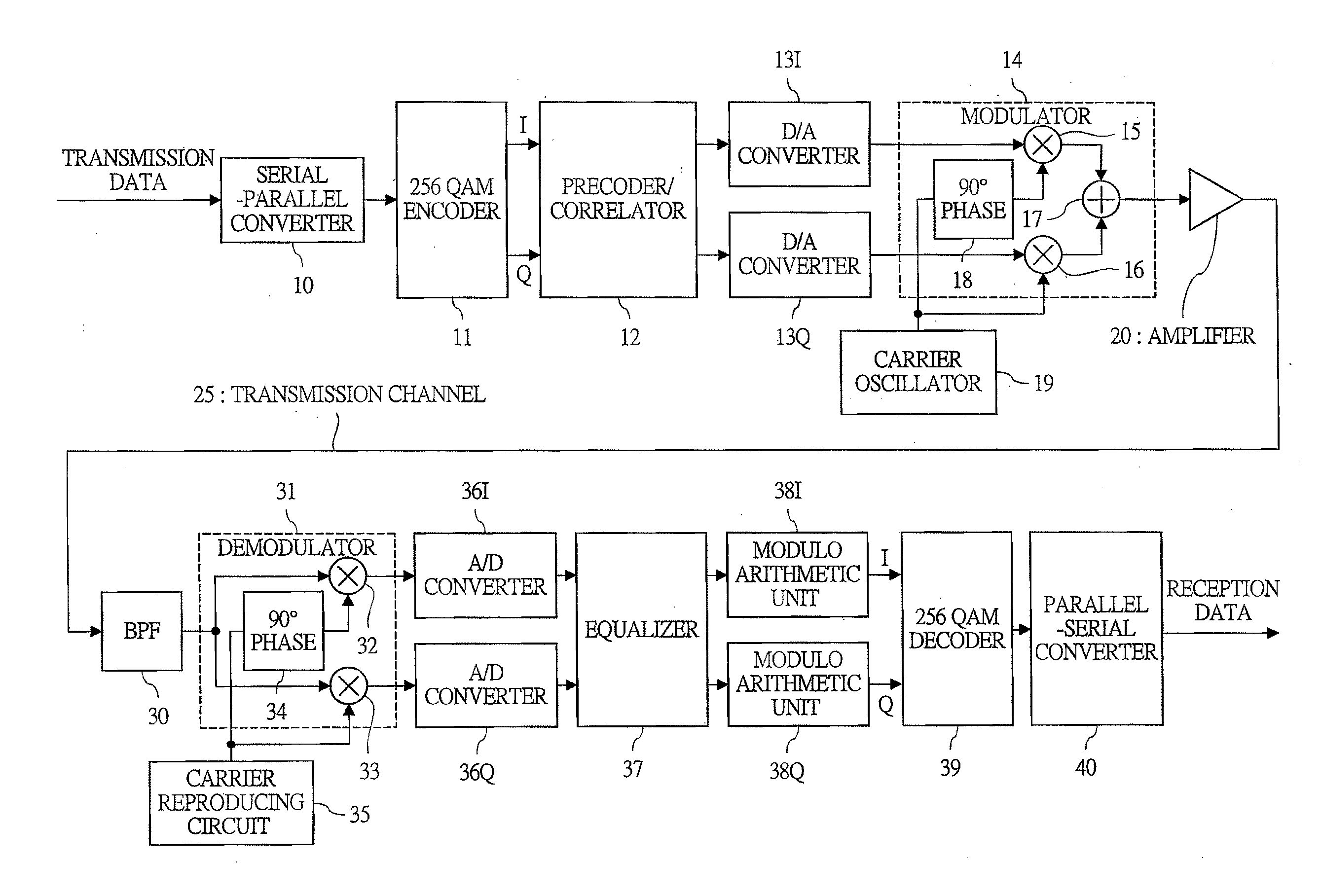
[0062]the present invention will be described below. FIG. 1 is a block diagram showing the configuration of the embodiment of the signal transmission apparatus of the present invention. An upper part of FIG. 1 corresponds to a sending unit and a lower part thereof corresponds to a receiving unit. Digital transmission data is converted to, for example, an 8-bit parallel signal by a serial-parallel converter 10. The 8-bit parallel signal is inputted to a 256 QAM encoder 11, and the 256 QAM encoder 11 converts the signal to a 256 QAM signal having 16×16 lattice by a known method and outputs signals I and Q.

[0063]A precoder / correlator 12, details of which will be described later, performs the processes according to the present invention to the signals I and Q so as to obtain a desired notch characteristic. The function and process of the sending unit except the precoder / correlator 12 are the same as those of a conventional QAM sending unit. Note that the processes before the precoder / co...

third embodiment

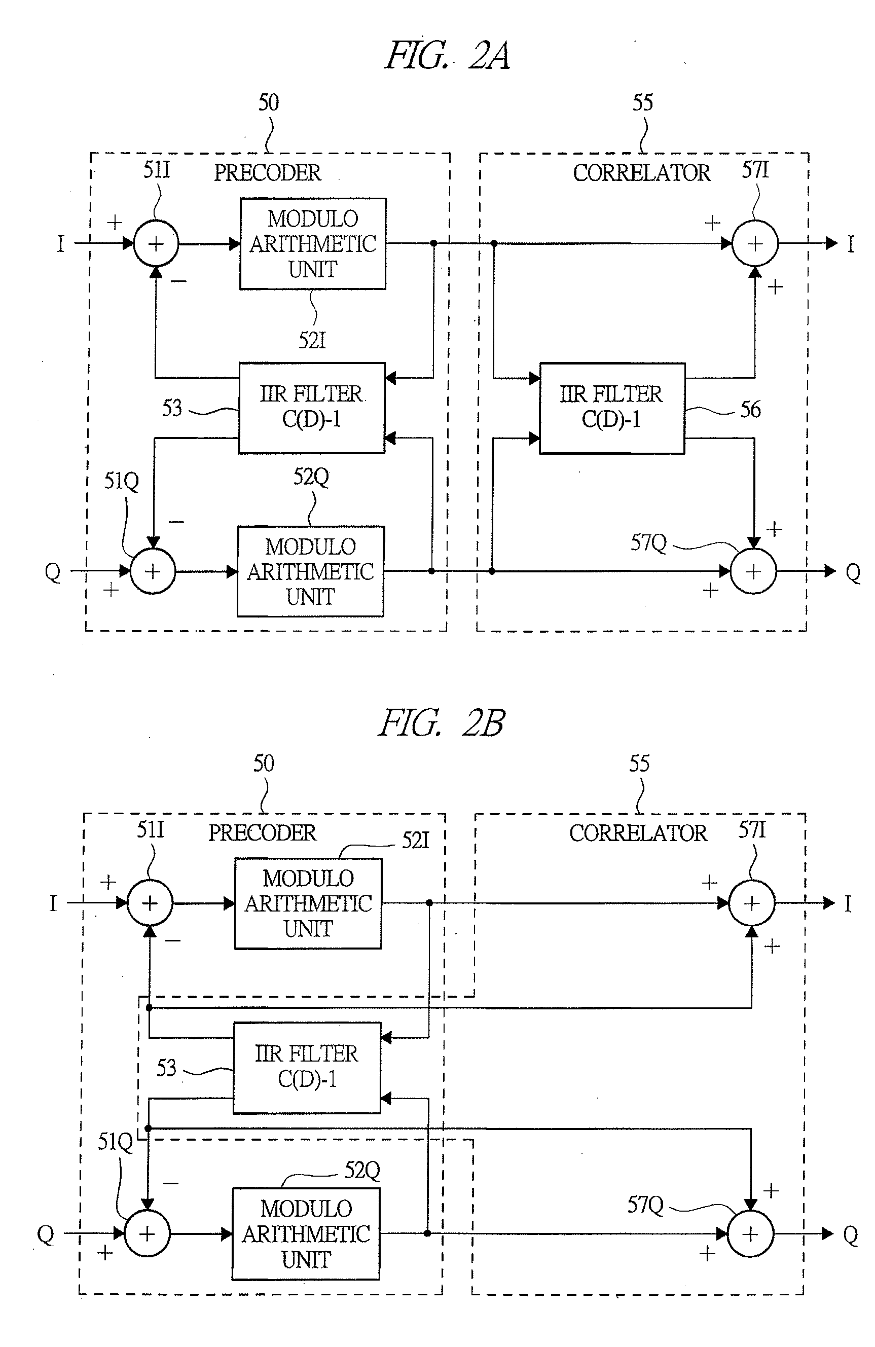
[0109]FIG. 14 is a block diagram showing the configuration of the precoder / correlator 180 of the modified embodiment. The block of the precoder / correlator 180 of the modified embodiment is the same as that of the third embodiment shown in FIG. 9B. However, the transfer function set in an IIR filter of a precoder 190 is a product between transfer functions CT(D) and CF(D) corresponding to variable notch characteristic and fixed notch characteristic which suppress the transmission signal and a transfer function CR(D) corresponding to the notch characteristic which suppresses the external noise signal in the receiving unit.

[0110]More specifically, the signal to be inputted to an adder 191 is [CT(D)*CF(D)*CR(D)−1]. On the other hand, the signal to be inputted to an adder 196 of a correlator 195 is [CT(D)*CF(D)−1]. Therefore, the transmission signal has the notch characteristic corresponding to the transfer function [CT(D)*CF(D)].

[0111]Note that, in the present invention, CT(D) is a tran...

fourth embodiment

[0126]In the fourth embodiment, with using the data transmission periods (A) to (C) to each MODEM in FIG. 15, the notch frequency is measured cyclically or when the transmission quality is deteriorated. FIG. 11 is a flow chart showing the contents of the null point search process 2 of the present invention. In this process, the notch frequency is moved at a slow speed which the equalizer on the receiving side can follow in the master MODEM, and a time position in which the transmission quality is optimum on the receiving side is detected, and then, this time position is converted to the notch frequency.

[0127]In S30, the master MODEM determines whether or not a predetermined time elapses after a previous process, and when a determination result is negative, the procedure proceeds to S30. On the other hand, when it is positive, the procedure proceeds to S31. In the meantime, whether or not the transmission quality is deteriorated below a predetermined value may be determined instead. ...


PUM


Abstract

A signal transmission apparatus of the invention comprises: a correlator 12 for shaping a spectrum of a signal; and a precoder 12 disposed on a previous stage of the correlator and including an adder which subtracts an output signal of a feedback filter from an input signal, a modulo arithmetic unit which inputs an output signal of the adder and executes modulo arithmetic operation, and the feedback filter which inputs an output signal of the modulo arithmetic unit and is provided with a transfer function obtained by subtracting 1 from a transfer function of the correlator. The correlator may be IIR filter means having a desired notch characteristic. By disposing a correlator which can freely shape a transmission signal spectrum containing a deep notch and suppress only a specified band on a receiving side, the suppression of an external noise can also be realized.

Description

CROSS REFERENCE TO RELATED APPLICATIONS[0001]This application is entitled to the benefit of and incorporates by reference essential subject matter disclosed in International Patent Application No. PCT / JP2006 / 314223 filed on Jul. 19, 2006; Japanese Patent Application No. 2005-222991 filed Aug. 1, 2005; and Japanese Patent Application No. 2006-002122 filed Jan. 10, 2006.TECHNICAL FIELD[0002]The present invention relates to a signal transmission apparatus and a signal transmission method. More particularly, it relates to a signal transmission apparatus and a signal transmission method capable of effectively transmitting signals while suppressing a transmission power or an external noise of a specified band in a usable frequency band.BACKGROUND ART[0003]In recent years, attentions have been paid to the PLC (Power Line Communication) system. The PLC system is a data transmission system which bidirectionally connects each home and a relay station to the Internet or the like provided in an...

Claims


Application Information

Patent Timeline
IPC IPC(8): H04B1/04H04B1/02
CPCH04B3/54H04B2203/5416H04B2203/5425H04L27/34H04B2203/5495H04L25/03828H04L27/2601H04B2203/5491
Inventor SATO, YOICHIHIGUCHI, TETSUYA
Owner NAT INST OF ADVANCED IND SCI & TECH
Why Eureka
Try Eureka