Method of monitoring and/or determining the condition of a force-measuring device, and force-measuring device

Active Publication Date: 2010-01-07
METTLER TOLEDO GMBH
View PDF19 Cites 15 Cited by
  • Summary
  • Abstract
  • Description
  • Claims
  • Application Information

AI Technical Summary

Benefits of technology

[0013]The disclosed devices and methods therefore have the objective to provide a simple and cost-effective met

Problems solved by technology

If the measurement device is installed in industrial systems with a high degree of automation, a failure of the measuring device can lead to a long downtime period of the system or can cause defective products.
These scales are normally used outdoors and are therefore particularly exposed to changing environmental conditions.
In addition, the exposure entails the immediate risk that these weighing modules can be hampered in their ability to function correctly due to improper manipulations such as intentional, negligent or erroneous acts of mistreatment or intrusion.
However, in case of a manipulation error it is possible that for example a liquid may penetrate into the interior of the housing, whereby the relative humidity in the interior space of the housing may increase to such an extent as to cause corrosion of the force-measuring cell or electronic components of the signal-processing circuitry.
If the devices are exposed to inappropriate ambient conditions during transportation and storage, it is possible that condensation will occur in the interior of the housing which can critically compromise the measurement performance.
To conduct an inspection of the force-measuring cell invol

Method used


Image

  • Method of monitoring and/or determining the condition of a force-measuring device, and force-measuring device
  • Method of monitoring and/or determining the condition of a force-measuring device, and force-measuring device
  • Method of monitoring and/or determining the condition of a force-measuring device, and force-measuring device

Examples


Embodiment Construction

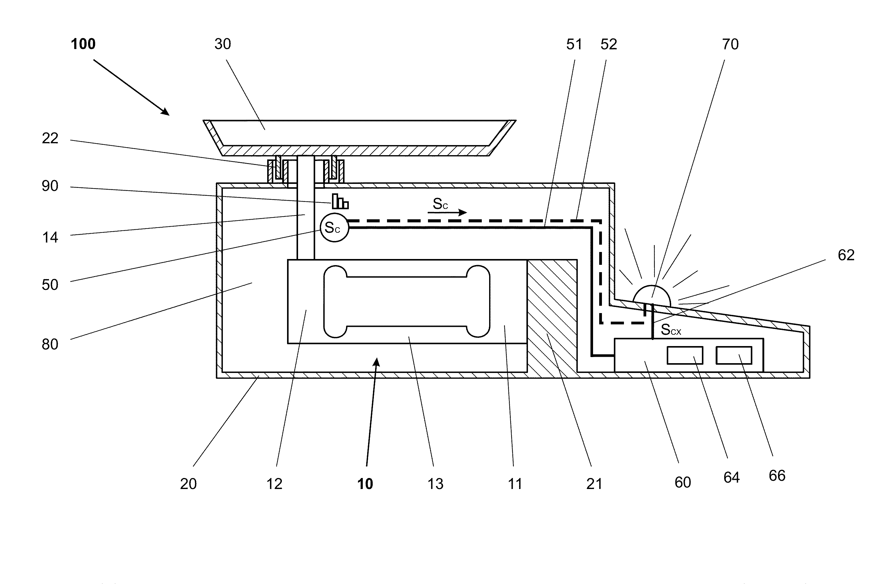
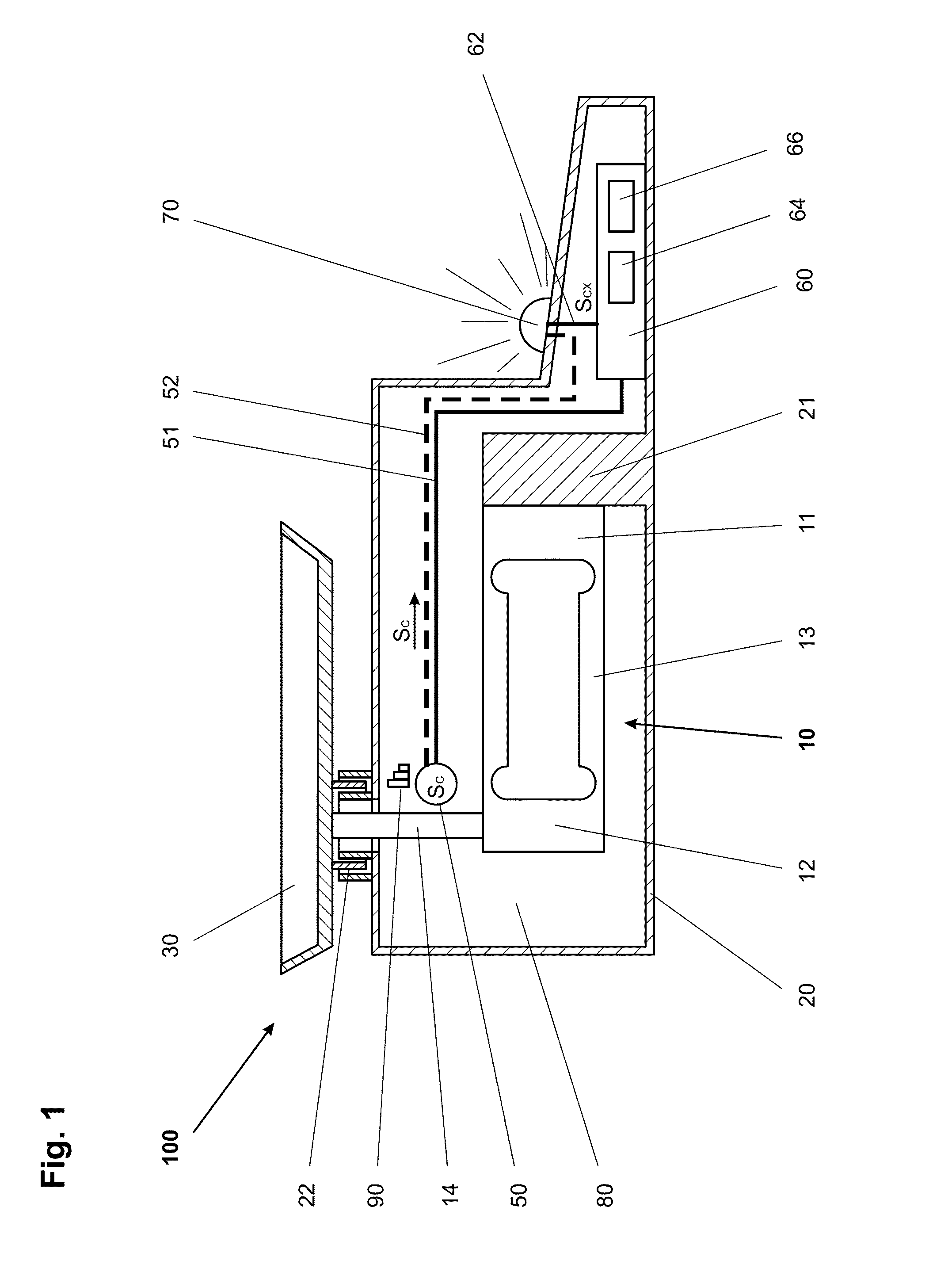
[0073]FIG. 1 schematically illustrates a force-measuring device 100, specifically a balance, in a sectional view. A force-measuring cell 10 includes a stationary part 11 and a load-receiving part 12 that are connected to each other by a mid-section 13. The force-measuring cell 10 is arranged in the interior space 80 of a housing 20 and its stationary part 11 is rigidly connected to the housing 20 by way of the support 21 which is a fixed part of the housing. A load receiver 30 in the form of a weighing pan which is arranged outside of the housing 20 is connected by way of a force-transmitting rod 14 to the load-receiving part 12 of the force-measuring cell 10 which is arranged in the interior space. By way of a passage opening 22, the force-transmitting rod 14 passes through the housing 20 without touching the latter. The passage opening 22 of the housing is configured in such a way that the penetration of dirt, dust and moisture is avoided as much as possible or is at least strongl...


PUM


Abstract

An interior space of the at least one housing of a force-measuring device is filled with a gas composition that is distinguishable in at least one parameter from the ambient atmosphere. A sensor that is arranged in the interior space, or on the housing, measures this distinguishable parameter. A processing unit of the force-measuring device compares signals obtained from the sensor to monitor and determine the condition of the force-measuring device.

Description

CROSS-REFERENCE TO RELATED APPLICATIONS[0001]This application is a continuation under 35 USC §120 of PCT / EP2008 / 052774, filed 7 Mar. 2008, which is in turn entitled to benefit of a right of priority under 35 USC §119 from European patent application 102007014711, filed 23 Sep. 2007. The content of each of the applications is incorporated by reference as if fully recited herein.TECHNICAL FIELD[0002]The disclosed embodiments define a method whereby the condition of a force-measuring device can be monitored or determined. The force-measuring device has at least one housing with an interior space in which at least one force-measuring cell is installed. The disclosure further concerns a force-measuring device that is suitable to carry out the method.BACKGROUND OF THE ART[0003]The term “force-measuring cell” means a measurement transducer which converts a force presented as an input quantity for example into an electrical signal as an output quantity. Specifically, a force-measuring cell ...

Claims


Application Information

Patent Timeline
IPC IPC(8): G01L1/00G01G23/01G01N25/18
CPCG01G21/30G01G23/01G01G23/3728
Inventor LOHER, URSJENSEN, KURTZIEBART, VOLKER
Owner METTLER TOLEDO GMBH
Why Eureka
Try Eureka