
Storage System

a storage system and data technology, applied in memory allocation/allocation/relocation, high-level techniques, instruments, etc., can solve the problems of reducing the response time of the access to online data, and affecting the performance of the response. , to achieve the effect of reducing the response tim

Active Publication Date: 2010-01-07
HITACHI LTD
View PDF10 Cites 10 Cited by
  • Summary
  • Abstract
  • Description
  • Claims
  • Application Information

AI Technical Summary

Benefits of technology

[0009]Therefore, the conventional disk array subsystem has a possibility that online data may be stored in an HDD applying the mode that shuts down the power supply to the HDD, which is a power saving mode having a high power saving effect but taking time for response. Then, when an access request to the online data occurs from the server, there is a possibility that the performance of response to the access to the online data may be reduced, and the access from the server may timeout.
[0010]Accordingly, it is an object of the present invention to provide a storage system having a function of saving power to a storage device and control method therefor, which do not reduce the performance of response to an access from a server to the storage device.
[0013]According to the invention, there can be provided a storage system having a function of saving power to a storage device and control method therefor, which do not reduce the performance of response to an access from a server to the storage device.

Problems solved by technology

Since the conventional disk array subsystem may not determine before data storage whether the archive data to be written from the server is online data that requires a high accessibility from the server, offline data that requires a lower accessibility from the server or near-line data that requires the accessibility between online data and offline data from the server, data cannot be stored in an HDD having an appropriate power saving function.
Then, when an access request to the online data occurs from the server, there is a possibility that the performance of response to the access to the online data may be reduced, and the access from the server may timeout.

Method used


Image

  • Storage System
  • Storage System
  • Storage System

Examples


Embodiment Construction

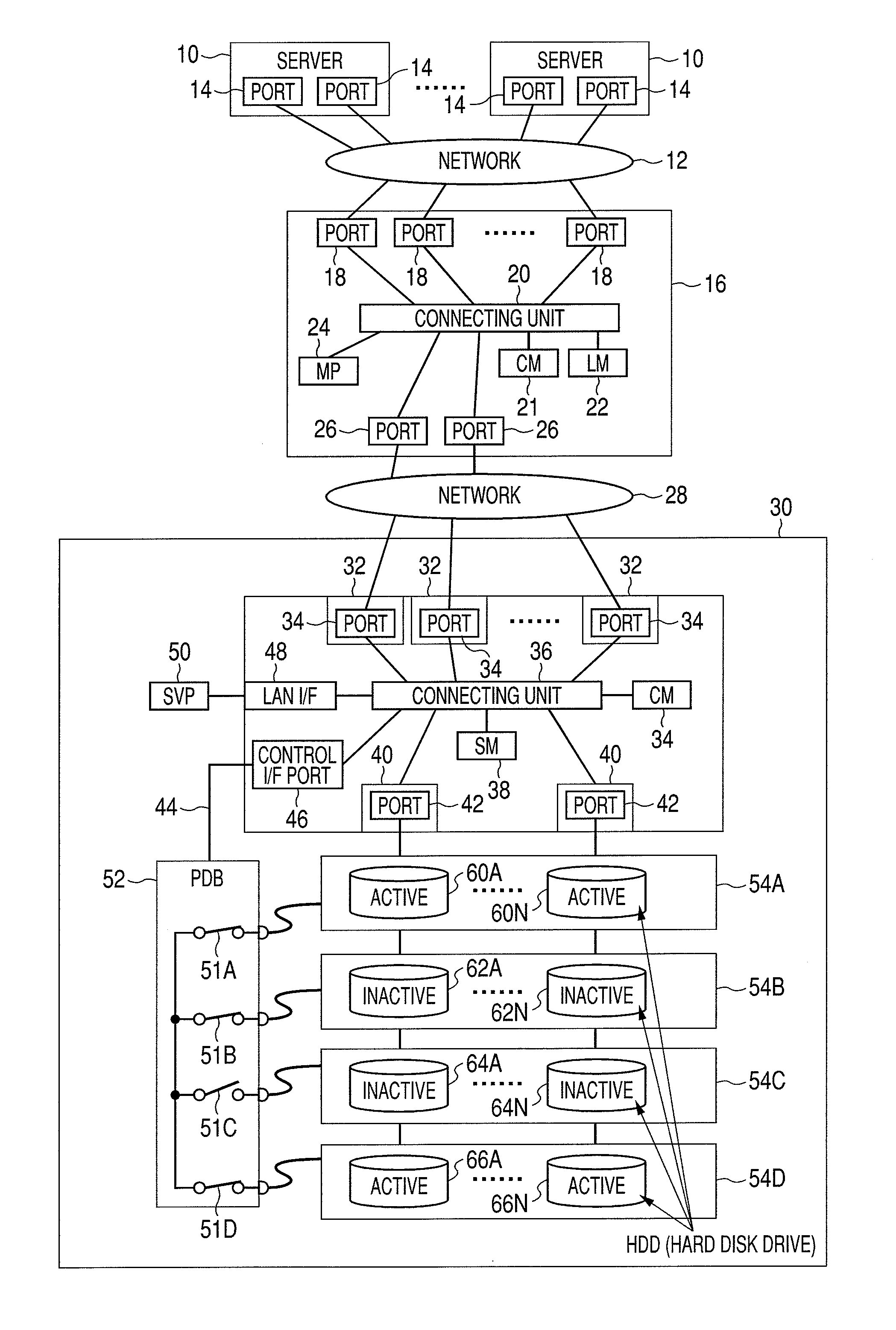
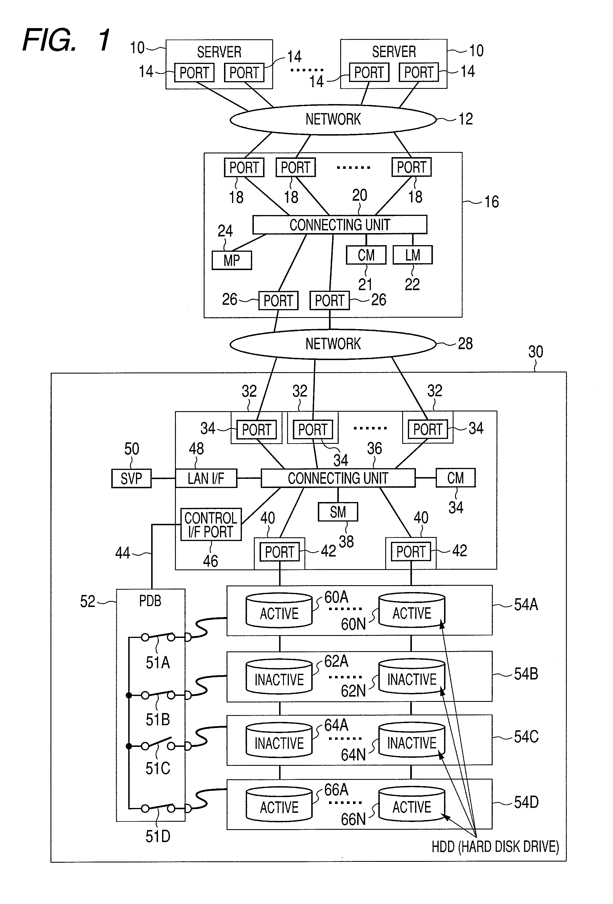
[0031]Embodiments of the invention will be described next. FIG. 1 is a block diagram of a storage control system including an example of the storage system according to the invention. The storage control system includes a service server 10 positioned as a host system for a storage apparatus and a storage system including a file server 16 and a storage apparatus 30. The file server 16 and the storage apparatus 30 may be placed within one chassis.

[0032]The service server 10 is a computer apparatus including information processing resources such as a CPU and a memory. The service server includes an information input device such as keyboard switches, a pointing device and a microphone and an information output device such as a monitor and a speaker.

[0033]The service server 10 recognizes the storage structure with a file system of the file server 16 and writes and reads data to and from the file system. The service server 10 may include archiving software for providing an archive solutio...


PUM


Abstract

There is provided a storage system including a file server connecting to a computer over a network and a storage apparatus connecting to the file server connecting over the network, wherein the file server includes a first controller, the storage apparatus includes multiple storage devices having multiple storage areas and a second controller that controls accesses to the multiple storage areas, each of the multiple storage areas has at least one power saving mode among multiple power saving modes with different shift times from the power saving modes to a ready mode, the first controller, in response to the reception of data from the computer, sets an indicator relating to the performance of response to an access from the computer to the data and refers to the indicator of the data and selects a first storage area having the power saving mode satisfying the indicator, and the second controller stores the data to the first storage area.

Description

CROSS REFERENCES TO RELATED APPLICATIONS[0001]This application relates to and claims priority from Japanese Patent Application No. 2008-177423, filed on Jul. 7, 2008, the entire disclosure of which is incorporated herein by reference.BACKGROUND OF THE INVENTION[0002]The present invention relates to a storage system, and it particularly relates to a storage system having a power saving function for a storage device and a control method therefor.[0003]Hitherto, a storage system has been known that includes a server and a disk array subsystem including an array of multiple hard disk drives (which will be called HDD hereinafter) for providing storage areas to the server.[0004]The server uses the disk array subsystem for multiple applications, and one application is that the server uses the disk array subsystem for archiving. By the way, keeping the HDDs on at all times which are not frequently accessed is not preferable from the viewpoint of power saving in the disk array subsystem. Acc...

Claims


Application Information

Patent Timeline
Patent Type & Authority Applications(United States)
IPC IPC(8): G06F1/32G06F12/02G06F12/16
CPCG06F1/3203G06F1/3268G06F3/0611G06F3/0625G06F3/0634Y02B60/32G06F3/0649G06F3/067Y02B60/1246H04L67/1097G06F3/0643Y02D10/00Y02D30/50
Inventor INNAN, MASATAKAHOMMA, SHIGEOSHIMADA, AKINOBUTABUCHI, HIDEO
Owner HITACHI LTD
Learn More