Joining unit

a technology of joining unit and component, applied in the direction of automatic control device, feeding apparatus, dynamo-electric machine, etc., can solve the problems of affecting the operation of the unit, the damage of the component of the joining unit, and the relatively complex system in which external units perform essential control functions, etc., to achieve simple and cost-effective construction, high functionality and safety of us

Active Publication Date: 2010-01-14
KISTLER HLDG AG
View PDF8 Cites 12 Cited by
  • Summary
  • Abstract
  • Description
  • Claims
  • Application Information

AI Technical Summary

Benefits of technology

[0012]The object underlying the present invention is a joining unit of the type mentioned in the beginning that not only has a high functionality and safety of use but also a simple and cost-effective construction.

Problems solved by technology

It is an essential disadvantage of such joining units that the functional control thereof is primarily performed via external units.
Due to the time required for the processing of the signal in the external unit as well as the time for signal transmission between the joining unit and the external unit it may be possible that the emergency shut-off is not actuated in time thus resulting in damages of components of the joining unit due to excessive straining by force.
Moreover, a system in which essential control functions are performed by external units is relatively complex and, therefore, difficult to handle by the user.

Method used


Image

  • Joining unit
  • Joining unit
  • Joining unit

Examples


Embodiment Construction

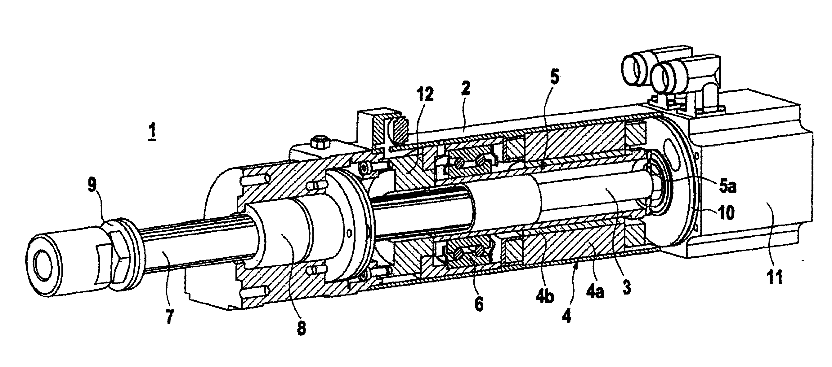
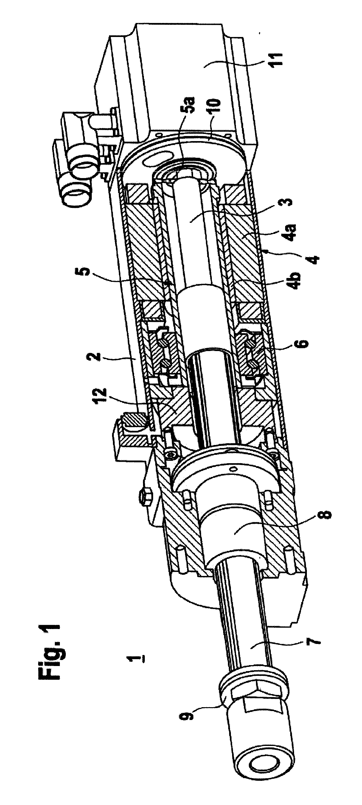
[0036]FIG. 1 shows an example of a joining unit 1. The joining unit 1 is integrated into an axially symmetric housing 2.

[0037]A spindle 3 is placed in the interior of the housing 2 the longitudinal axis of which extends in the axis of symmetry of the housing 2. Preferably, the spindle 3 is embodied as a ball bearing screw or a planetary roller drive.

[0038]Driving of the spindle 3 is performed by means of a hollow shaft motor 4 and, thus, without any use of a gear. The hollow shaft motor 4 is in the form of an electric drive. In the present case, the electric drive is embodied as a servo motor. The stator 4a of the electric drive is arranged at the inner wall of the housing 2 and concentrically with the spindle axis. A tubular body 5 is firmly connected with the spindle 3. The tubular body 5 is essentially in the form of a hollow cylinder the lateral surface of which is arranged concentrically with and in a predetermined distance to the spindle 3. At its front face the tubular body 5...


PUM

PropertyMeasurementUnit
forcesaaaaaaaaaa
force/displacementaaaaaaaaaa
forceaaaaaaaaaa

Abstract

A joining unit contains a spindle drive in the form of a hollow shaft motor that encloses a spindle. The hollow shaft motor serves to achieve a linear movement of a joining tool for the execution of a joining process. The joining unit contains instruments for the presetting and/or determination of the forces exerted and/or the movement of the joining tool during the joining process.

Description

CROSS-REFERENCE TO RELATED APPLICATIONS[0001]This application claims priority to International Application Serial No. PCT / EP2006 / 007029 filed Jul. 18, 2006.TECHNICAL FIELD[0002]The invention relates to a joining unit according to the main part of claim 1.BACKGROUND[0003]A joining unit of this type is known from DE 203 05 789 U1.[0004]The joining unit described therein contains a spindle drive for the generation of a linear movement of a joining tool. The spindle drive is formed by a hollow shaft motor that encloses a spindle.[0005]The hollow shaft motor is embodied as an electric drive and encompasses a stator as well as a rotor which is firmly attached to the spindle. The rotor causes the spindle to execute a rotational movement.[0006]For the generation of the linear movement of the joining tool a plunger is provided that forms the lower surface of a tubular housing insert having an interior space through which a portion of the spindle extends. A nut is provided at the upper side o...

Claims


Application Information

Patent Timeline
Patent Type & Authority Applications(United States)
IPC IPC(8): B23P19/02B30B1/18B30B15/00
CPCB23P19/02Y10T29/53909B30B15/0094H02K7/06H02K11/0042Y10T29/53848Y10T29/53061Y10T29/5373Y10T29/5383Y10T29/53843Y10T29/53943Y10T29/53657Y10T29/5377Y10T29/53678B30B1/186H02K11/24
Inventor MULLER, ALEXANDER
Owner KISTLER HLDG AG
Why Eureka
Try Eureka