Axial air gap machine having stator and rotor discs formed of multiple detachable segments

a stator disc and axial air gap machine technology, which is applied in the direction of stator/rotor body manufacturing, magnetic circuit rotating parts, and magnetic circuit shape/form/construction, etc., can solve the problems of schmidt et al.'s limited torque motor, impede the manufacturing, assembly and transportation of electrical equipment with a large diameter rotor, etc., to achieve low speed and improve blade efficiency.

Inactive Publication Date: 2010-01-14
CLEAN CURRENT PARTNERSHIP
View PDF14 Cites 82 Cited by
  • Summary
  • Abstract
  • Description
  • Claims
  • Application Information

AI Technical Summary

Benefits of technology

[0026]The stator armature windings may be connected per each phase in parallel, series or series-parallel connections. Depending on the connection mode, the same mechanical arrangement of the stator and of the rotor may be connected to (as a generator) or from (as a motor) power sources of different nominal voltages. In general, the windings of the stator armatures are permitted to be decoupled from one another thermally and magnetically. These multi-phase AC machines may also have their phase-windings decoupled magnetically and thermally. This decoupling feature enhances the fault-tolerance of the machine, and permits redundancy to be built into the machine such that the machine may be operated with a desired degree of redundancy.
[0040]The direct drive (no drive shaft) feature may be implemented in a machine using bearings (of different types) arranged on the stator frame and rotor. Advantages of direct drive include rendering possible the use of the double-sided axial configuration in applications where usage of shaft is not possible or not desired due to structural challenges. The use of the direct drive (no drive shaft) feature, including use of the direct drive features in machines of large diameter, allows (by stator fragmentation) low speed and high torque applications to operate at grid electrical frequency, and at various levels of voltage across the machine terminals and current through the stator windings.

Problems solved by technology

However, the torque motor of Schmidt et al. is limited to the electrical components of electrical windings and iron cores in each stator segment.
Schmidt et al. is also limited to a single-piece annular rotor, which impedes the manufacturing, assembly and transportation of electrical equipment having a large diameter rotor.

Method used


Image

  • Axial air gap machine having stator and rotor discs formed of multiple detachable segments
  • Axial air gap machine having stator and rotor discs formed of multiple detachable segments
  • Axial air gap machine having stator and rotor discs formed of multiple detachable segments

Examples


second embodiment

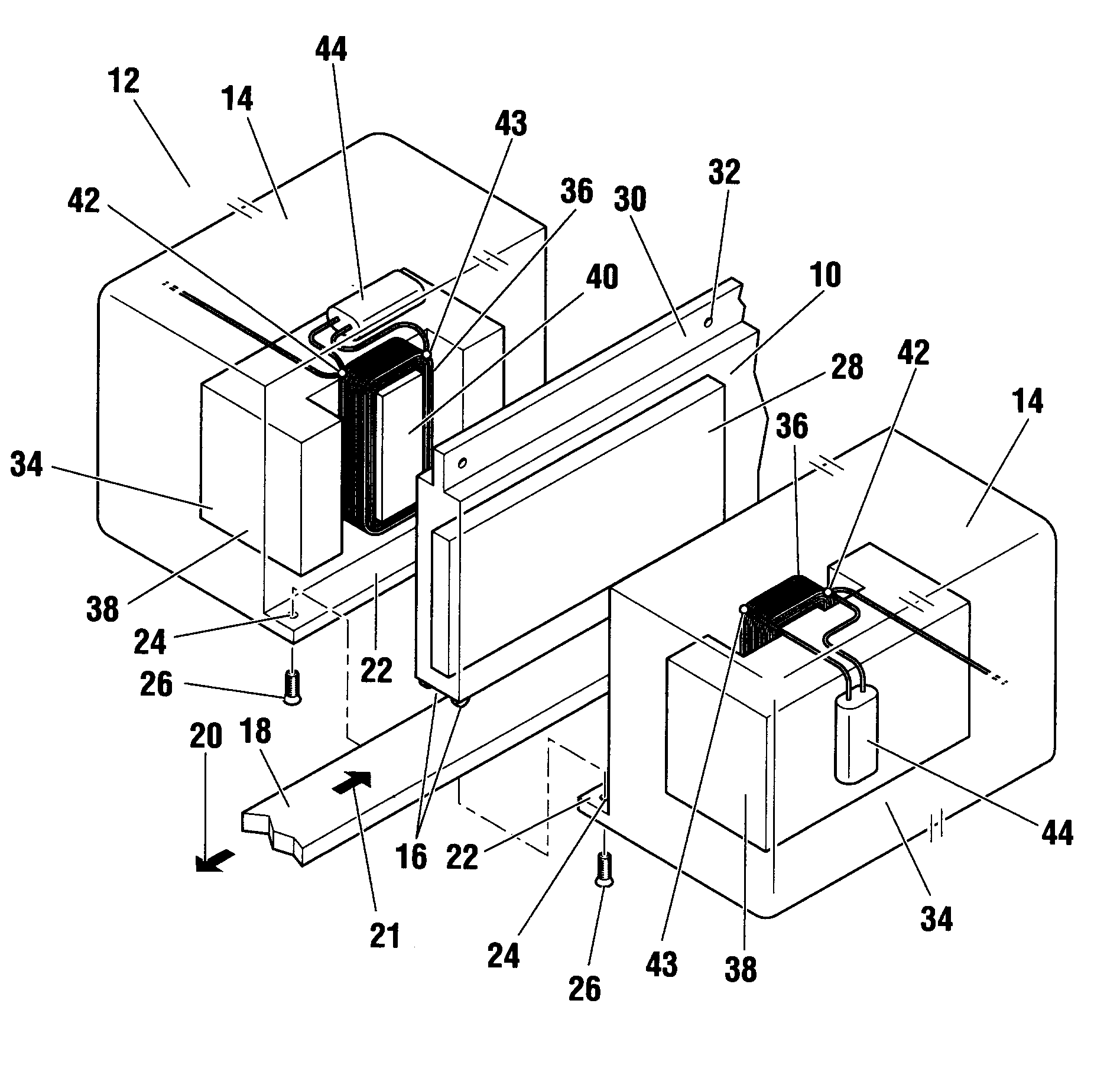
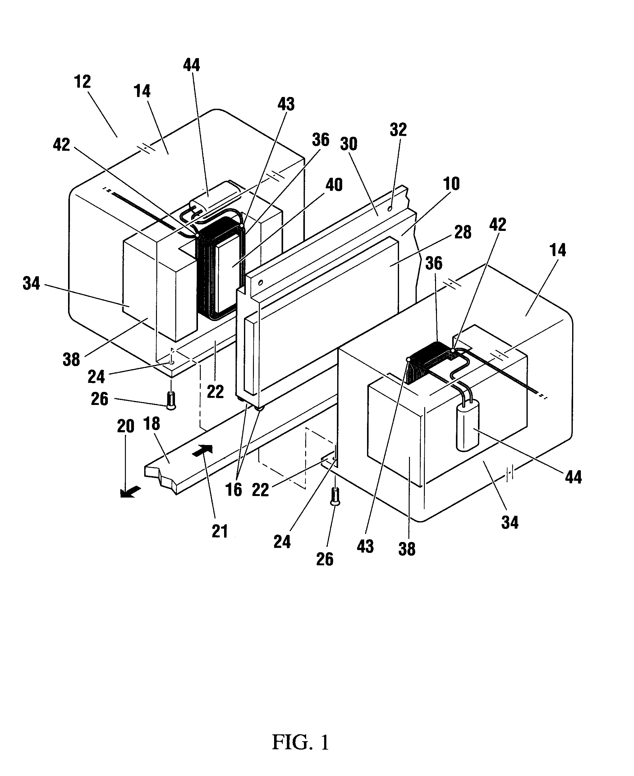
[0101]FIG. 10 shows the rotor segment 10 disposed between the stator segments 14 of the pair 12 in accordance with a second embodiment of the invention. The stator segments 14 may be integrally formed as a single unit, as shown in FIG. 10, or may be separated and attached to each other or attached to the support structure 18. A fluid, such as the fluid lubricant 140 shown in FIG. 10, fills the gap 142 between the rotor segment 10 and the pair 12 of stator segments 14. A pair of seals 144 disposed on either side of the rotor segment 10 in the gap 142 prevent leakage of the fluid lubricant 140. The fluid lubricant 140 is used to slidably couple the rotor segment 10 and the pair of stator segments 14 such that the rotor segment 10 is operable to move relative to the pair of stator segments 14 without contacting either stator segment 14. The fluid lubricant 140 may be under pressure to prevent contact between the rotor segment 10 and either stator segment 14. At least at the outer surfa...


PUM

PropertyMeasurementUnit
diametersaaaaaaaaaa
diametersaaaaaaaaaa
diametersaaaaaaaaaa

Abstract

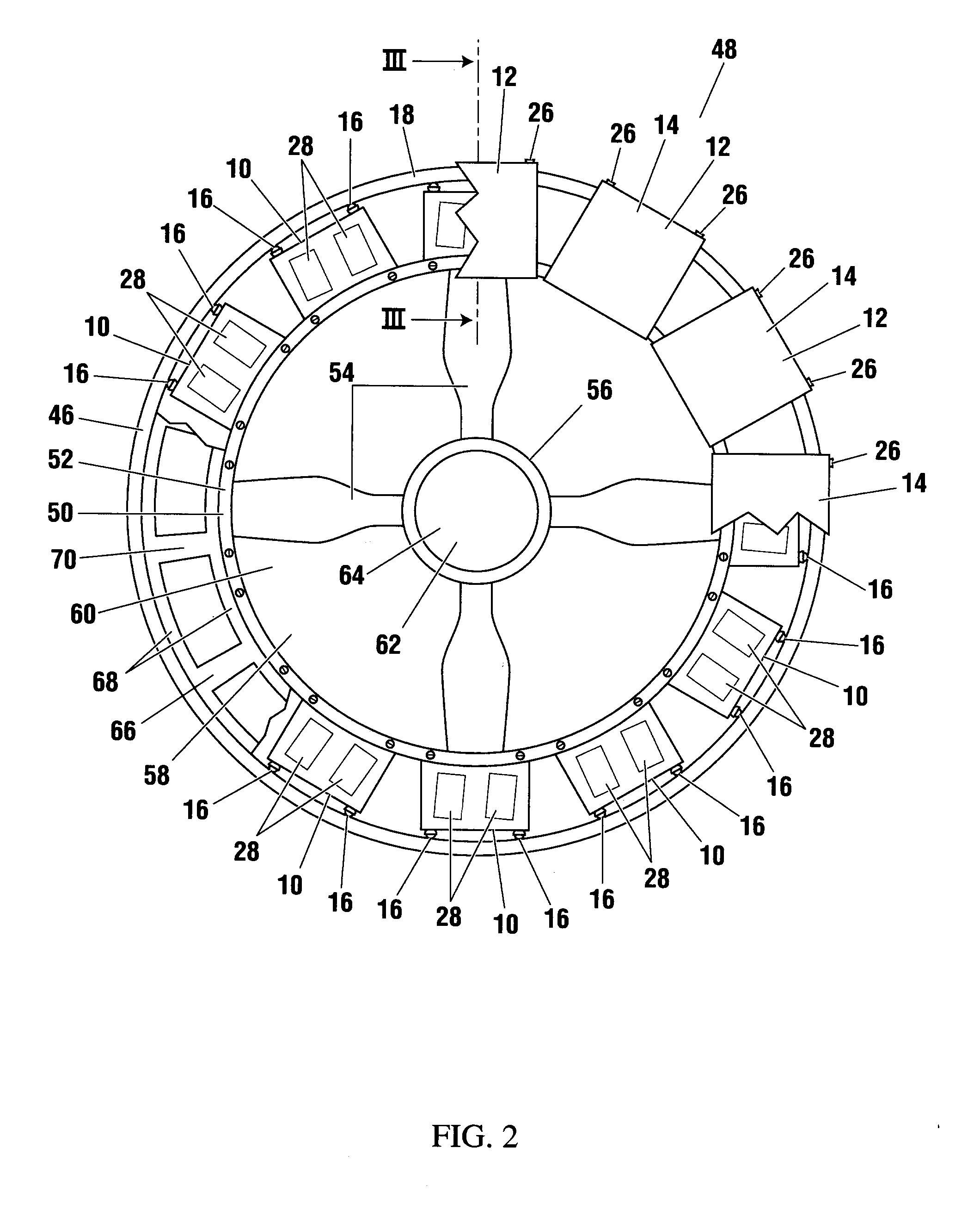
A generator or motor apparatus having a stator formed of a plurality of pairs of parallel stator segments is provided The pairs of parallel segments are connected together to form a channel in which an annular rotor moves The annular rotor also comprises a plurality of detachable segments connected together to form an annular tram operable to move through said channel Each stator segment comprises a stator winding set and each rotor segment comprises a magnet dimensioned to fit between the parallel spaced apart stator segments The apparatus may include a support structure, the rotor segments being slidably coupled to the support structure and the stator segments being attached the support structure The apparatus may be a rim generator, wind turbine generator or other electrical machine The stator winding set includes a winding, and may include other electrical or electronic components, including possibly a power factor capacitor, direct current filtering capacitor, supercapacitor, and one or more diodes The stator winding set nay be encapsulated within the stator segment

Description

BACKGROUND OF THE INVENTION[0001]1. Field of Invention[0002]This invention relates to rotor and stator components of electrical generators and electrical motors and, in particular, to rotor segments and stator segments for a generator and / or motor.[0003]2. Description of Related Art[0004]Many electrical generators for generating direct current (DC) and alternating current (AC) electricity and many AC and DC motors have been developed. Some generators and motors include permanent magnets located along the circumference of a rotor mounted on a drive shaft and electrical wire windings or coils located along an inner side of an annular stator. An external force such as flowing air or water rotating the drive shaft and rotor induces electrical current in the coils, thereby generating electricity. When electrical current is passed through the coils, the resulting magnetic force on the permanent magnets causes rotation of the rotor and drive shaft, which acts as the output shaft of a motor...

Claims


Application Information

Patent Timeline
Patent Type & Authority Applications(United States)
IPC IPC(8): H02K15/12H02K21/24H02K1/28H02K1/18H02K11/00H02K15/02
CPCH02K1/14Y10T29/49012H02K1/2793H02K5/08H02K11/0094H02K11/046H02K16/02H02K16/04H02K21/24H02K41/031H02K2201/15Y02E10/725H02K7/1869H02K2213/06H02K2213/12Y10T29/49009H02K1/18Y02E10/72H02K11/049H02K1/2796H02K15/02H02K21/46H02K1/06H02K1/12H02K1/27
Inventor PLATON, MIHAI C.YOUNG, VIRGIL F.
Owner CLEAN CURRENT PARTNERSHIP
Why Eureka
Try Eureka