Buck converter threshold detection for automatic pulse skipping mode

a threshold detection and automatic pulse skipping technology, applied in the direction of efficient power electronics conversion, electric variable regulation, instruments, etc., to achieve the effect of high selection flexibility

Active Publication Date: 2010-01-14
DIALOG SEMICONDUCTOR GMBH
View PDF26 Cites 15 Cited by
  • Summary
  • Abstract
  • Description
  • Claims
  • Application Information

AI Technical Summary

Benefits of technology

[0015]A principal object of the present invention is to achieve a high flexibility in selecting thresholds for switching between entering and leaving a discontinuous current mode (DCM).

Problems solved by technology

It is a challenge for the designers of buck converters to detect the optimal threshold for entering and leaving the discontinuous current mode (DCM) and to implement a fast way for switching back to CCM.

Method used


Image

  • Buck converter threshold detection for automatic pulse skipping mode
  • Buck converter threshold detection for automatic pulse skipping mode
  • Buck converter threshold detection for automatic pulse skipping mode

Examples


Embodiment Construction

[0030]The preferred embodiments disclose methods and systems to detect a threshold for entering and leaving a discontinuous current mode (DCM) or pulse frequency modulation control mode (PFM) of a buck converter by measuring an average battery current.

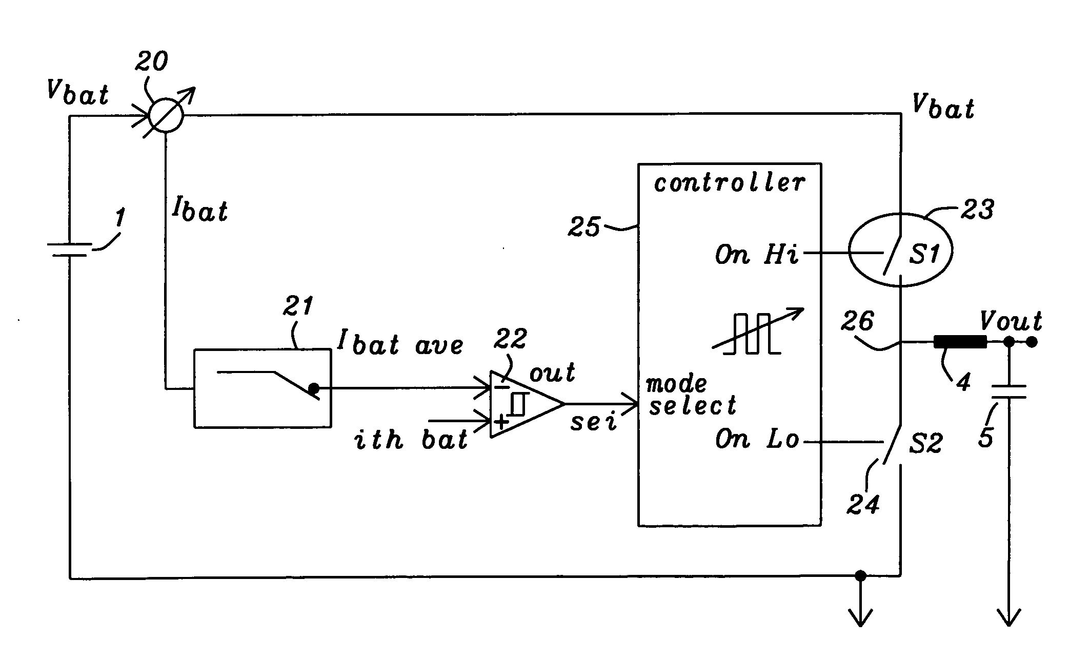
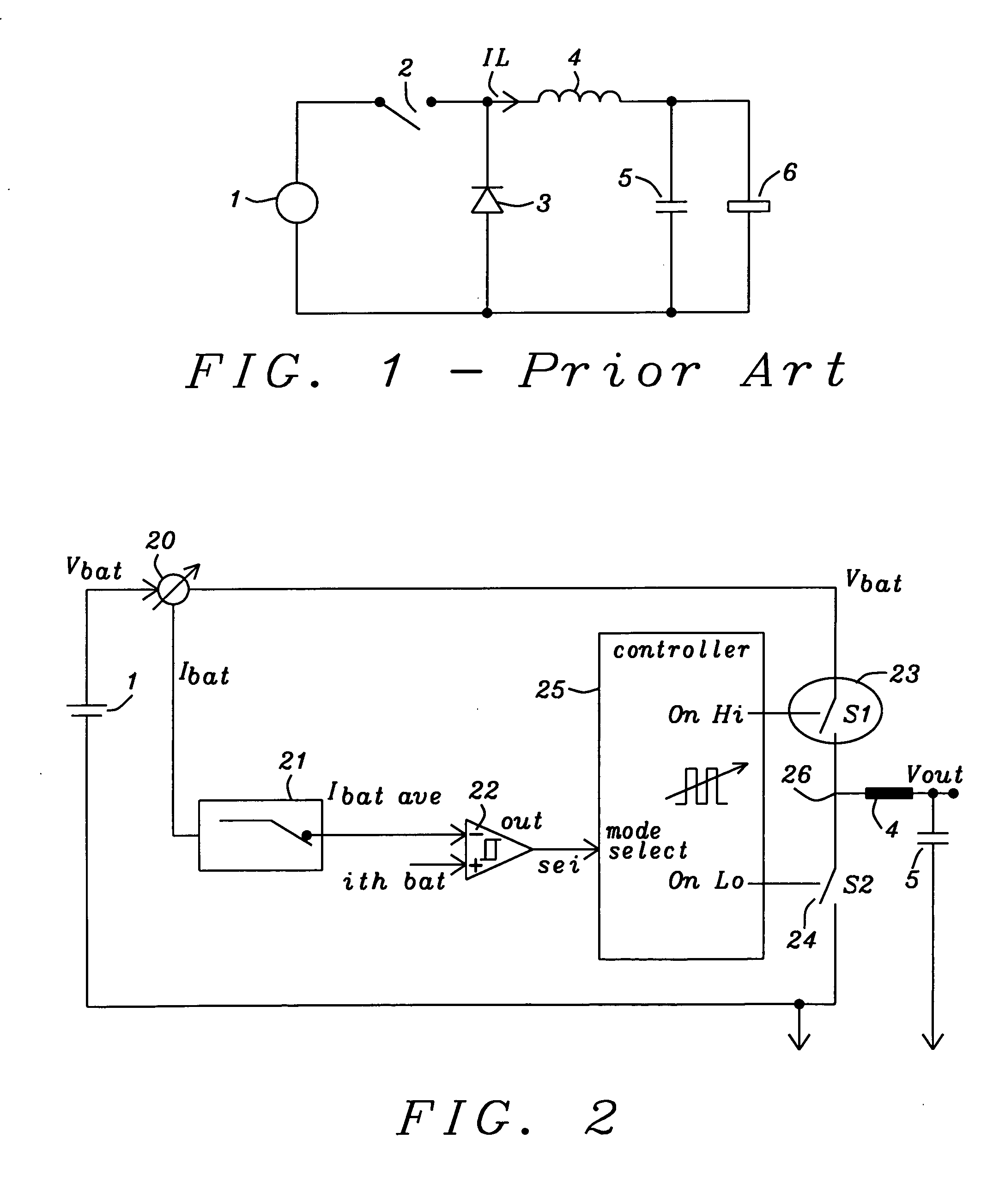
[0031]FIG. 2 illustrates a block diagram showing the principal building blocks of the threshold detection invented for automatic DCM mode. The block diagram comprises a battery (obviously or any other DC voltage source) 1 providing a battery voltage Vbat, an inductor 4, usually a coil, and a capacitor 5, being connected between the output voltage Vout and ground. Furthermore the block diagram comprises a high side switch 23 and a low side switch 24, wherein both high side and low side switches are controlled by a controller 25. This controller 25 controls these switches for DCM and CCM mode. The selection of DCM or CCM mode is dependent upon the output of a current comparator 22. This comparator 22 compares a reference current Ithbat w...


PUM


Abstract

Circuits and methods to detect a threshold for entering and leaving a discontinuous current mode of a buck converter have been disclosed. A buck converter is switched to continuous mode if the filtered battery current has reached a defined threshold current Ithccm. In order to expedite the transition from DCM mode to CCM mode the time delay between two or more pulses of a current through an inductor is monitored and the buck converter is switched to CCM mode if this time delay is smaller than a defined threshold.

Description

BACKGROUND OF THE INVENTION[0001](1) Field of the Invention[0002]This invention relates generally to the field of DC-to-DC converters and relates more specifically to buck converters switching with a high flexibility between continuous current mode and discontinuous current mode.[0003](2) Description of the Prior Art[0004]A buck converter is a step-down DC to DC converter. It is a switched-mode power supply that uses in its basic implementation two switches (usually a transistor and a diode), an inductor and a capacitor.[0005]FIG. 1 prior art illustrates the basic layout of a buck converter. A buck converter comprises a DC voltage source (usually a battery), a switch 2, a diode 3,an inductor 4, often an output capacitor 5, to keep the output voltage constant, and a load 6. The operation of a buck converter alternates between connecting the inductor 4 via switch 2 to source voltage 1 to store energy in the inductor 4 and discharging the inductor 4 into the load 6.[0006]A buck convert...

Claims


Application Information

Patent Timeline
Patent Type & Authority Applications(United States)
IPC IPC(8): G05F1/62
CPCH02M3/156H02M3/158Y02B70/10H02M1/0032
Inventor FAERBER, MARTIN
Owner DIALOG SEMICONDUCTOR GMBH
Why Eureka
Try Eureka