Controlling the temperature of electrical and
mechanical components - particularly during operation of the components - has always been a problem and especially within the art of wind energy
converters, this problem has been profound.
Often the same wind energy converter type has to be able to operate in both extremely hot and extremely cold areas of the globe, which makes heavy demands on the wind energy
converters system for controlling the temperature of especially wind turbine components such as gear, generator,
power handling equipment, bearings and other.
But the quality of the outside air is difficult to control both in temperature,
humidity, purity and other.
Furthermore, modern wind turbines get bigger and bigger in
power output and thereby often also in production of
excess heat and this matched with the fact that air is a relatively poor conductor of heat, make these types of cooling systems very large, expensive and heavy.
Even further, the fact that the temperature of the air outside the wind turbine varies a lot from site to site, from day to night and from season to season—in extreme cases from −30° to +50° Celsius—will in some cases result in wind energy
converters with an over-dimensioned and expensive cooling
system.
This problem could of course be overcome by adapting the
temperature control system of the wind energy converter to the specific erection site, but this would be logistically difficult, expensive and prolong the time of delivery of the wind energy converters.
But such a system is both complex and difficult to implement and since wind energy converters usually produce the majority of the power during the day (because of more wind during the day), it usually also needs the most cooling during the day, where the sun and the ambient temperature will heat up the surface of the wind turbine.
Such a system will therefore have to have a very large
cooling capacity to be able to work properly, making the system itself very large and expensive.
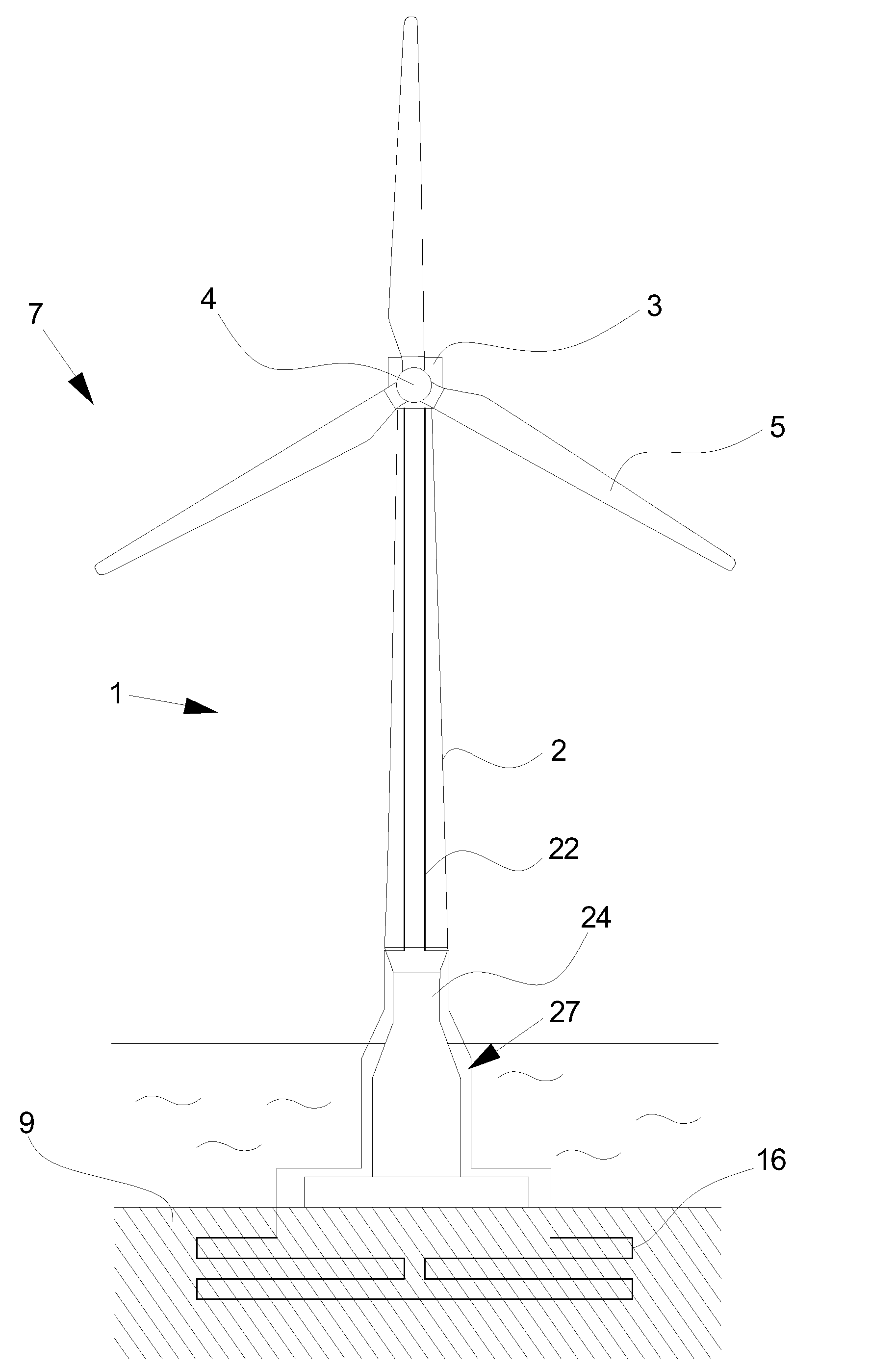
Regarding offshore wind energy converters it is known to use
seawater to cool different components of the wind turbine, but if the cooling system is open there are serious problems regarding ice, clogging,
corrosion and other, which are difficult and expensive to solved, and if the system is closed e.g. by circulating a
cooling medium through a hose placed in the
seawater there is ice,
storm, overgrowing and other to be solved.
The problems of both these systems being complicated and expensive to overcome and no matter how it is done, this technique is only feasible in relation to offshore wind energy converters.
But this cooling system is not very efficient and is contains several of the previously mentioned drawbacks such as difficulties in controlling the quality and other.

