
Fuel injection system

a fuel injection system and fuel injection technology, applied in the direction of machines/engines, mechanical equipment, lighting and heating apparatus, etc., can solve the problems of difficult to ensure efficient combustion of fuel, and achieve the effect of increasing the efficiency of the fuel injection system and optimizing the efficiency of the cruis

Active Publication Date: 2010-01-21
ROLLS ROYCE PLC
View PDF6 Cites 15 Cited by
  • Summary
  • Abstract
  • Description
  • Claims
  • Application Information

AI Technical Summary

Benefits of technology

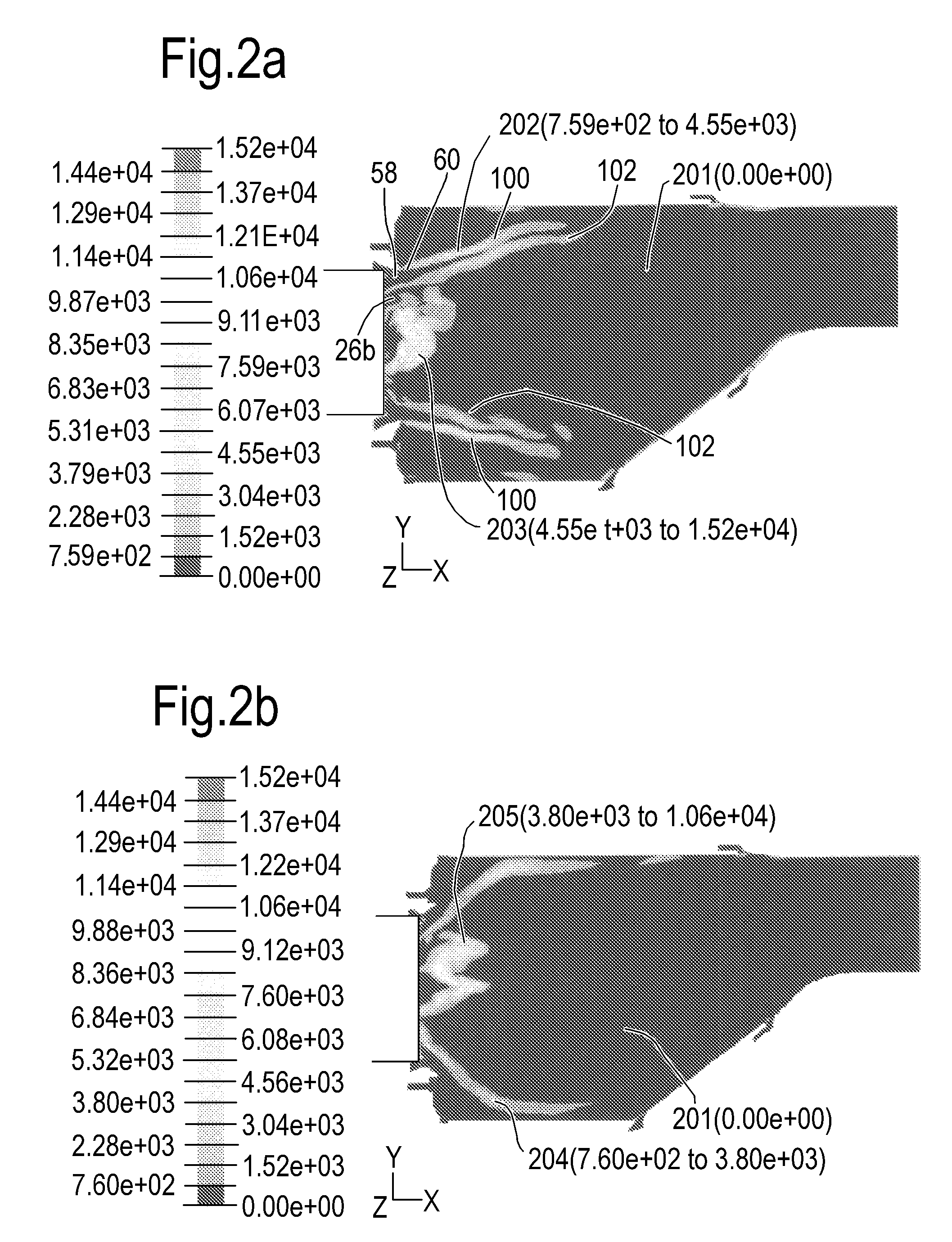
[0014]Thus, a double flame front is formed on the fuel spray stream. This is in contrast to known fuel injection systems which only produce a flame front on the radially inner surface of the fuel spray stream. As a result of this double flame front, the combustion efficiency of the fuel injection system may be improved and the amount of unburnt fuel reduced. Thus, the overall efficiency of the gas turbine may be increased, and there may be a reduction in the amount of unburnt hydrocarbons deposited on the inner surfaces of the combustion chamber and in the amount of exhaust smoke emitted.
[0040]Simplex pressure atomiser pilot fuel injectors have generally been found to be more suitable than pilot fuel airblast injectors for smaller gas turbine engines. This is because they allow the overall radial dimension of the fuel injector to be minimised, which is important for minimising the hole diameter through the engine case for insertion of the fuel injector.

Problems solved by technology

However, ensuring efficient combustion of the fuel can be difficult because the velocity of the air stream within the combustion chamber creates a hostile environment for the flame, while the short length of the combustion system means there is little time for burning to occur.

Method used


Image

  • Fuel injection system
  • Fuel injection system
  • Fuel injection system

Examples


Embodiment Construction

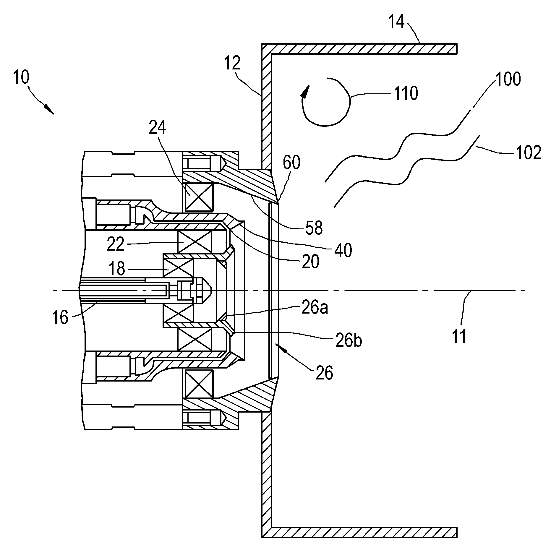
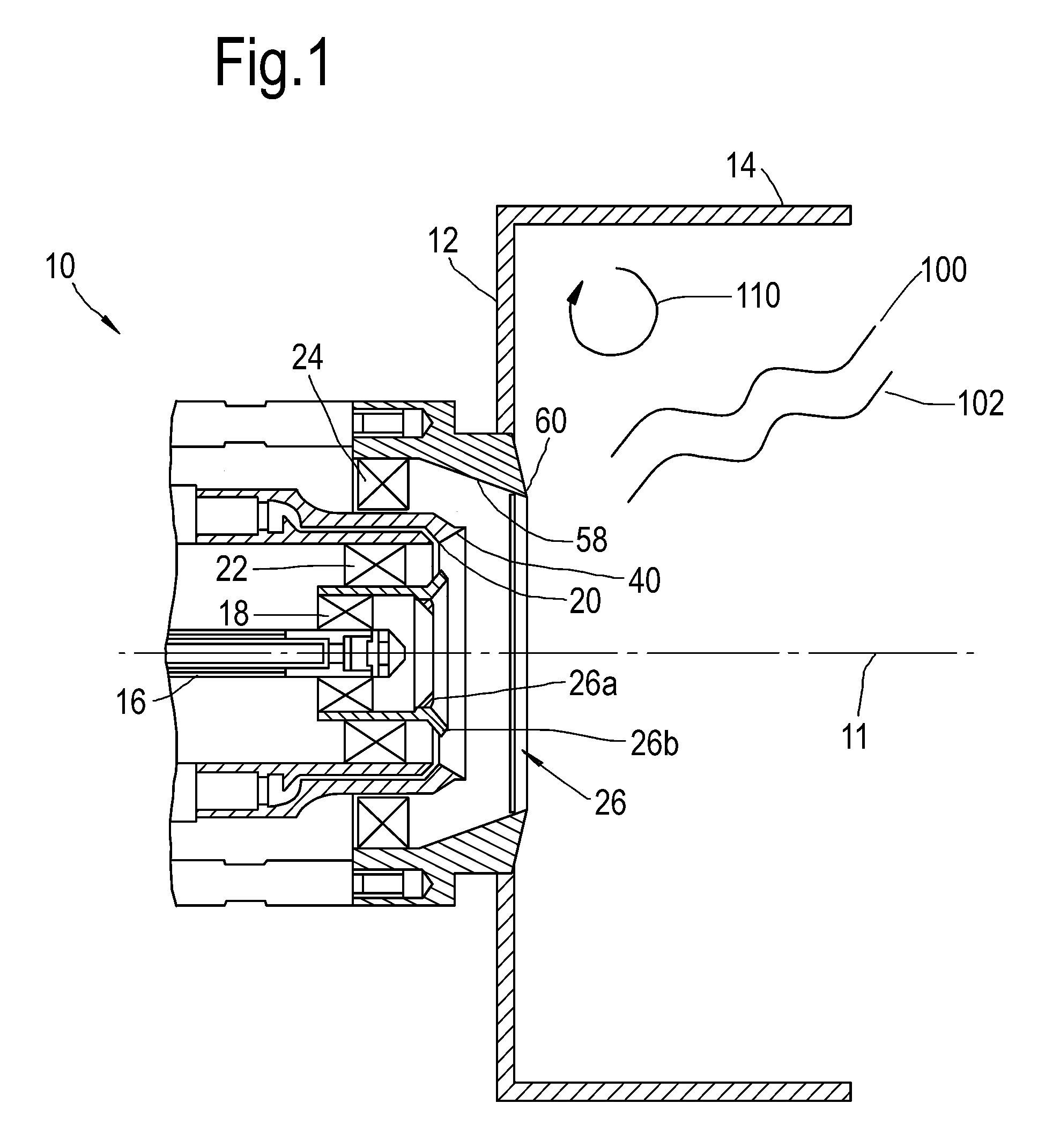
[0053]FIG. 1 shows a schematic view of a first embodiment of a fuel injection system 10 according to the present invention. The fuel injection system 10 is mounted on the upstream wall 12 of a combustion chamber i.e. at the head of a flame tube 14 of the combustion chamber of a gas turbine engine. The surface of the upstream wall 12 that faces in the downstream direction of the fuel injection system is clad with a heatshield.

[0054]Fuel injection system 10 has a central axis 11, and is in general circularly symmetrical about this axis. The fuel injection system 10 includes a pilot fuel injector 16. In this embodiment, the pilot fuel injector 16 may be a pressure atomiser fuel injector, such as a simplex pressure atomiser fuel injector, that atomises fuel based on a pressure differential placed across the fuel. The pilot fuel injector 16 shown in FIG. 1 is of this type. Alternatively, the pilot fuel injector may be a pilot fuel airblast injector that atomises fuel using a rapidly movi...


PUM


Abstract

A fuel injection system is provided for a gas turbine, comprising a mains airblast fuel injector having an annular shape, and inner and outer mains swirlers for swirling air past the mains airblast fuel injector. The inner and outer mains swirlers are concentric with the mains airblast fuel injector and are located radially inwardly and radially outwardly of the mains airblast fuel injector, respectively. The mains airblast fuel injector and the inner and outer mains swirlers are so arranged as to produce a fuel spray stream which expands from the mains airblast fuel injector and has a double flame front. The double flame front comprises flame fronts on both the radially inner and radially outer surfaces of the fuel spray stream.

Description

CROSS REFERENCE TO RELATED APPLICATION[0001]This application is entitled to the benefit of British Patent Application No. GB 0812905.8, filed on Jul. 16, 2008.FIELD OF THE INVENTION[0002]The present invention relates to fuel injection systems and particularly to fuel injection systems for gas turbine engines.BACKGROUND OF THE INVENTION[0003]Fuel injection systems deliver fuel to the combustion chamber of an engine, where the fuel is thoroughly mixed with air before combustion. One form of fuel injection system well-known in the art is a fuel spray nozzle. Fuel spray nozzles atomise the fuel to ensure its rapid evaporation and burning when mixed with air. However, ensuring efficient combustion of the fuel can be difficult because the velocity of the air stream within the combustion chamber creates a hostile environment for the flame, while the short length of the combustion system means there is little time for burning to occur.[0004]An airblast atomiser nozzle is a type of fuel spra...

Claims


Application Information

Patent Timeline
Patent Type & Authority Applications(United States)
IPC IPC(8): F02C7/22
CPCF23D11/107F23R3/343F23R3/28F23R3/14
Inventor GASHI, SARAPILATIS, NICKOLAOS
Owner ROLLS ROYCE PLC
Learn More