
Nanoporous carbonaceous membranes and related methods

a carbonaceous membrane and nanoporous carbon technology, applied in the field of nanoporous carbon compositions, can solve the problems of degrading the polymeric membrane, limiting the stability of polymeric materials, and reducing the stability of polymeric membranes

Inactive Publication Date: 2010-01-21
DREXEL UNIV
View PDF2 Cites 18 Cited by
  • Summary
  • Abstract
  • Description
  • Claims
  • Application Information

AI Technical Summary

Benefits of technology

The patent describes a membrane made of a cohesive carbon material with small pores that have a cross-sectional dimension of less than 7 nm. The membrane is formed by treating an inorganic carbon-containing precursor to remove non-carbon species and form a supported nanoporous carbon membrane with the small pores. The membrane can be used in various applications such as gas separation, sensors, and membrane reactors. The technical effect of this invention is the formation of a membrane with small pores that can provide improved performance in various applications.

Problems solved by technology

Polymeric membranes, however, have certain limitations.
Polymeric materials are also known to have less than optimal stability under intense thermal or chemical conditions.
In separation applications, the gases and liquids to be separated can degrade the polymeric membranes or lead to membrane fouling.
The presence of chlorine and extreme pH can also result in deterioration of polymer membranes.
Polymeric membranes often have a limited porosity, resulting in high flow resistance and increased energy requirements.
Additionally, consistent porosity within polymeric membranes is challenging to achieve.
However, composite membranes are hindered by the difficulties of achieving desirable adhesion between the polymer and particles and also of achieving uniform particle dispersion.
In addition, the thermal and chemical stabilities of polymer / ceramic composites are similar to polymer membranes and thus have the same disadvantages.
However, zeolites can be challenging to process, as they tend to crack, arising from their crystalline nature.
Furthermore, it is difficult to form thin zeolitic membranes, typically needed for creating high permeate flux.
Methods for synthesizing such membranes pose certain challenges, including: limitations of the membrane thickness to greater than about 20 micrometers for the supported membranes, the formation of cracks in the membranes, challenges in the controlling the pore sizes in the resultant membrane; and that the precursors of such membranes are typically limited to organic materials.

Method used


Image

  • Nanoporous carbonaceous membranes and related methods
  • Nanoporous carbonaceous membranes and related methods
  • Nanoporous carbonaceous membranes and related methods

Examples


example 1

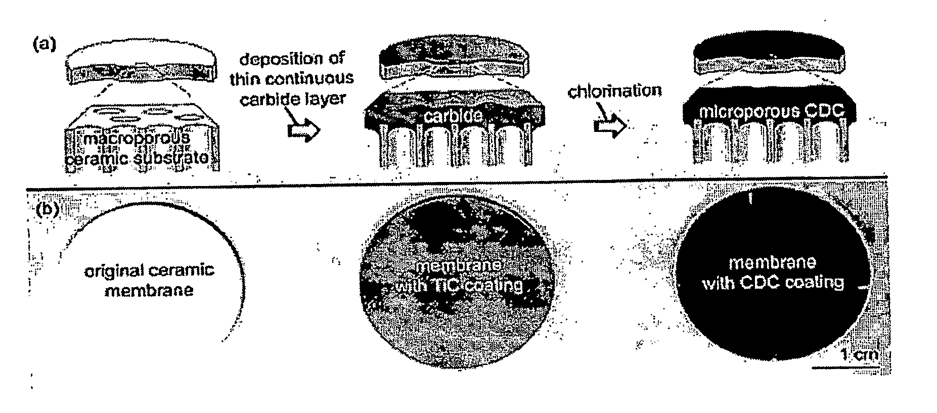
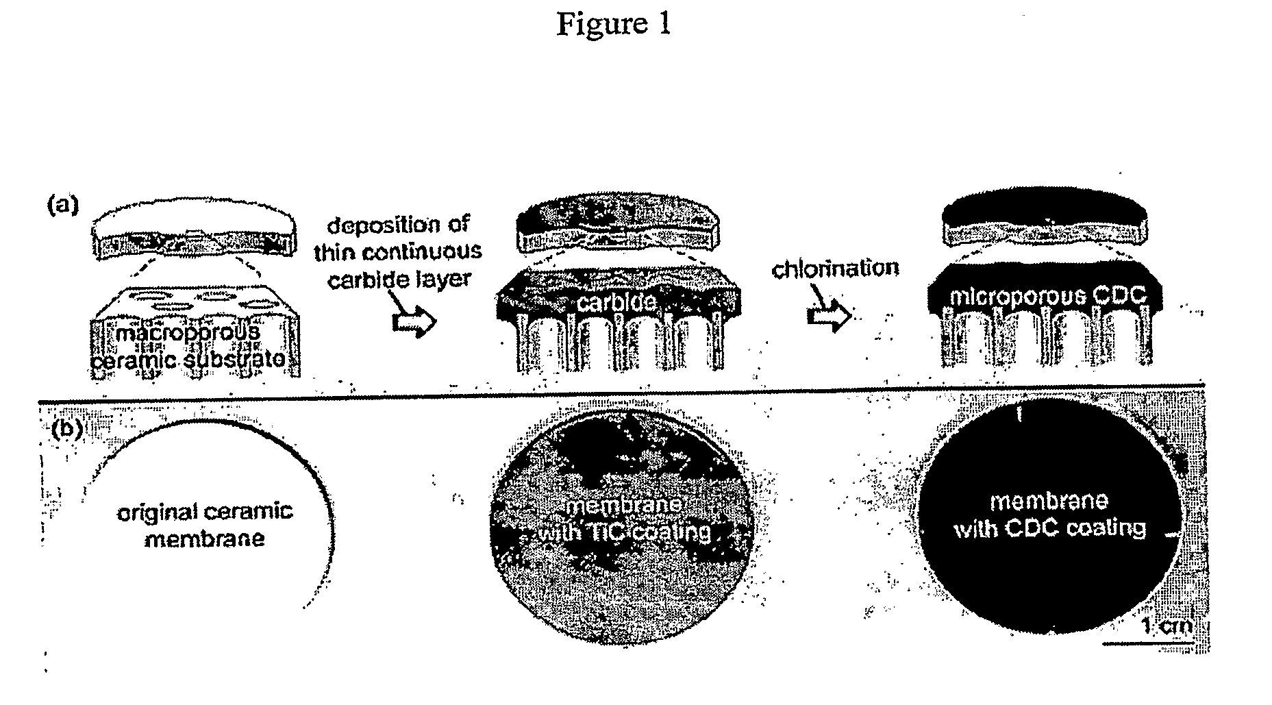
[0055]Samples were prepared according to the scheme in FIG. 1. Two porous ceramic substrates were used to support a CDC thin film. The first was a porous microfiltration substrate (Sterlitech Corporation, Kent, Wash.), 47 mm in diameter and 2.5 mm thick. The second, (Anodisc™ 25, Whatman International Ltd, Maidstone, England) had a diameter of 25 mm and 0.08 mm thickness. Prior to sputtering the inorganic carbon-containing precursor, the polypropylene ring around the Anodisc™ 25 substrate was removed by heating of the substrates to 600° C. in air for 5 minutes; the heating rate was 5° C. / min.

[0056]An approximately 500 nm layer of TiC was deposited on the substrates by magnetron sputtering. Wendler, B.; Danielewski, M.; Przybylski, K.; Rylski, A.; Kaczmarek, L.; Jachowicz, M., Journal of Materials Processing Technology, 2006, 175, 427. During sputtering, the ceramic support membranes were attached to a rotating table using a steel wire. The vacuum chamber was pumped down to a residua...

example 2

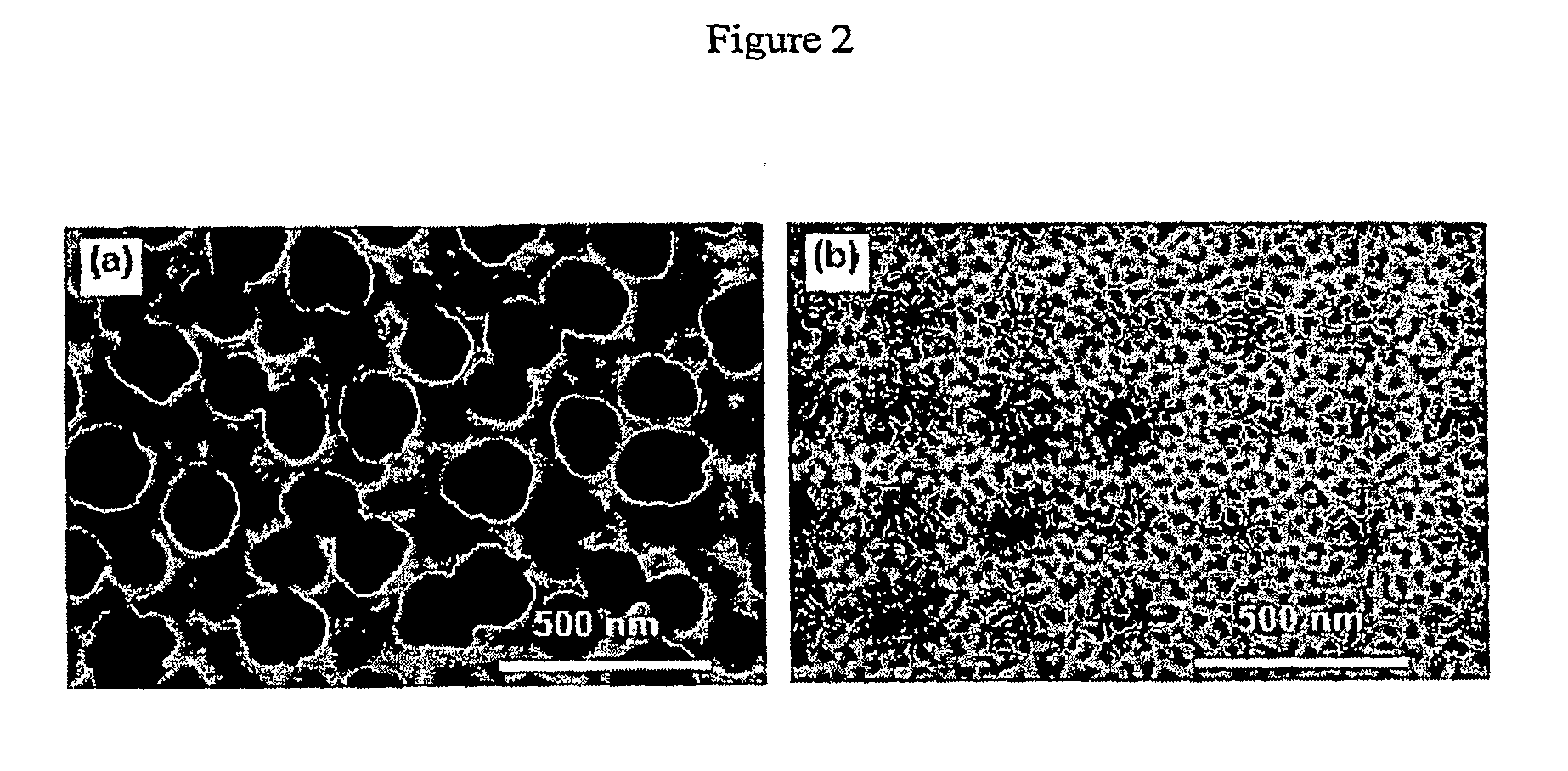
[0066]For the synthesis of nanoporous membranes, a uniform crack-free thin film of titanium carbide was applied onto a porous alumina disc, Anodisc™ 25 (Whatman International Ltd, Maidstone, England) using a magnetron sputtering technique. The film thickness was about 0.5 microns as determined by scanning electron microscope, see FIG. 3b.

[0067]The coated disc was loaded into the hot zone of a horizontal quartz tube furnace. The quartz tube inner diameter dimension was 25 mm. The tube was Ar purged for 30 minutes at approximately 60 sccm before heating at a rate of approximately 30° C. / minute up to the desired temperature. Once the temperature reached 400° C. and stabilized, the Ar flow was stopped and a 3-hour chlorination began in Cl2 flowing at a rate of 20 sccm. Evolved metal chlorides were trapped in a water-cooled condenser at the outlet of the heating zone. After the completion of the chlorination process, the samples were cooled under a flow of Ar to remove residual metal ch...

example 3

[0070]Nanoporous carbon membrane was prepared by chlorinating sintered 3 mm thick Ti3SiC2 ceramics at 1000° C. The coated disc was loaded into the hot zone of a horizontal quartz tube furnace. The quartz tube inner diameter dimension was 22 mm. The tube was Ar purged for 30 minutes at about 60 sccm before heating at a rate of approximately 30° C. / min up to 1000° C. Once the temperature reached 1000° C. and stabilized, the Ar flow was stopped and a 4-hour chlorination began in Cl2 flowing at a rate of 20 sccm. Evolved metal chlorides were trapped in a water-cooled condenser at the outlet of the heating zone. After the completion of the chlorination process, the samples were cooled under a flow of Ar to remove residual metal chlorides from the pores, and removed for further analyses. In order to avoid a back-stream of air, the exhaust tube was connected to a bubbler filled with sulfuric acid.

[0071]Filtration experiments were performed on the produced hydrophilic self-supported membran...


PUM

PropertyMeasurementUnit
thicknessaaaaaaaaaa
thicknessaaaaaaaaaa
thicknessaaaaaaaaaa

Abstract

Disclosed are nanoporous carbonaceous membranes and related devices, along with associated methods.

Description

CROSS-REFERENCE TO RELATED APPLICATIONS[0001]This application claims the benefit of U.S. Provisional Application No. 60 / 799,980, filed on May 12, 2006, the entirety of which is incorporated by reference herein.STATEMENT OF GOVERNMENT INTEREST[0002]The U.S. Government may have certain rights in the present invention. This work was partially supported by U.S. Department of Energy contract DE-FC36-04GO14282 and by National Science Foundation IGERT grant number DGE-0221664.FIELD OF THE INVENTION[0003]The present invention relates to the field of nanoporous carbon compositions. The present invention also relates to the field of carbon materials chemistry.BACKGROUND OF THE INVENTION[0004]Thin film membranes are industrially used in a variety of applications including purification of gases, water, biological fluids, organic and inorganic chemicals. For a variety of reasons, membranes comprised of polymeric resins are widely used in the field.[0005]Polymeric membranes, however, have certain...

Claims


Application Information

Patent Timeline
Patent Type & Authority Applications(United States)
IPC IPC(8): B01D71/02C23C16/32C23C16/34C23C14/34B32B3/26B01D67/00
CPCB01D53/228B01D67/0072B01D67/0093B01D2325/021B01D69/12B01D71/021B01D69/02Y10T428/249978Y10T428/249921
Inventor HOFFMAN, ELIZABETH NOLAYUSHIN, GLEBGOGOTSI, YURYBARSOUM, MICHEL W.
Owner DREXEL UNIV
Learn More