
Energy-resolving detection system and imaging system

a detection system and energy-resolving technology, applied in the field of energy-resolving detection systems for detecting radiation, can solve the problems of not providing any energy resolution, reducing the energy resolution of the energy-resolving detection system, and a limited range of intensities of radiation, so as to reduce the intensity of radiation reaching the second layer, increase the energy-resolution of the energy-resolving detection system, and reduce the effect of superposition

Inactive Publication Date: 2010-01-21
KONINKLIJKE PHILIPS ELECTRONICS NV
View PDF8 Cites 38 Cited by
  • Summary
  • Abstract
  • Description
  • Claims
  • Application Information

AI Technical Summary

Benefits of technology

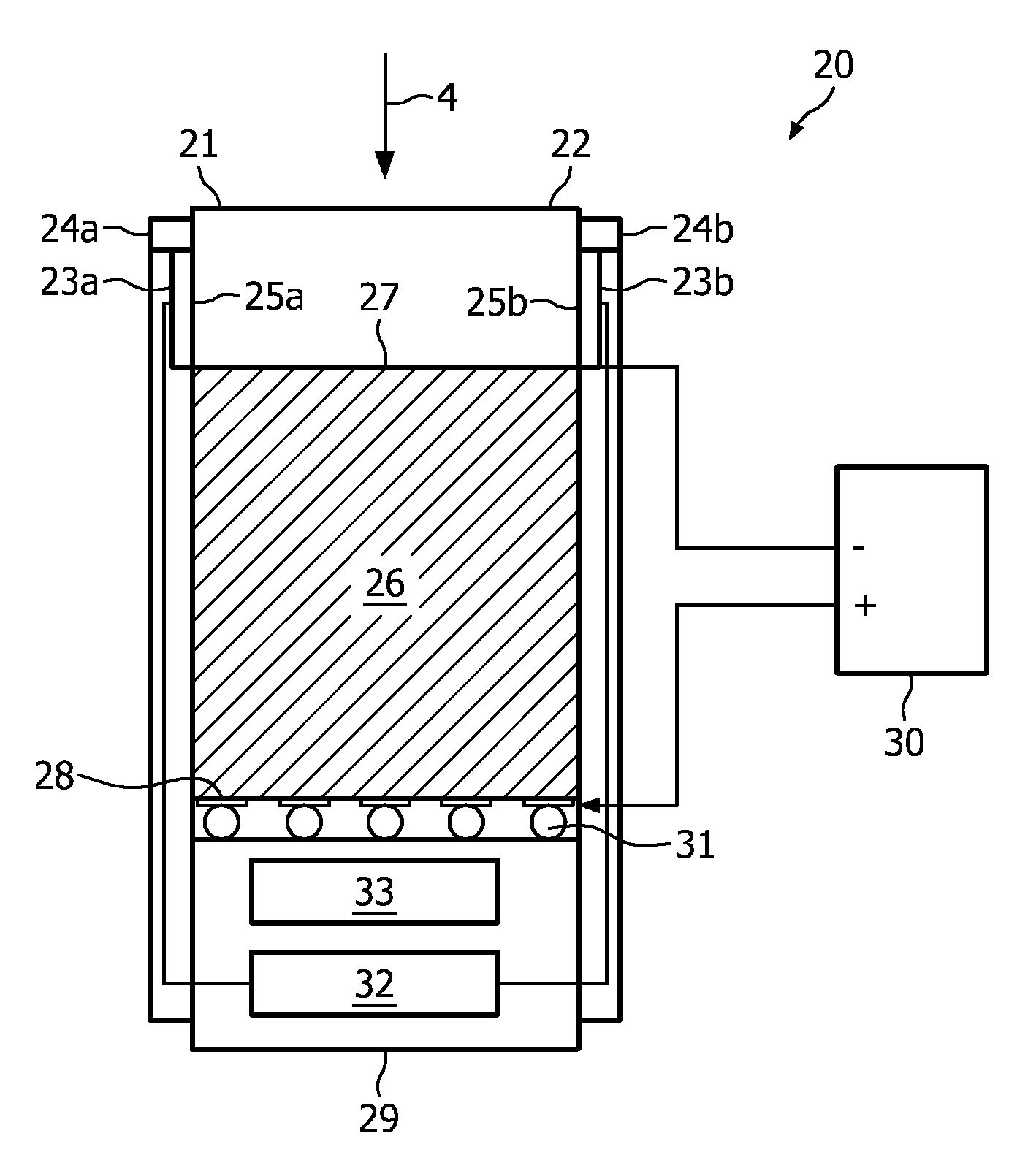
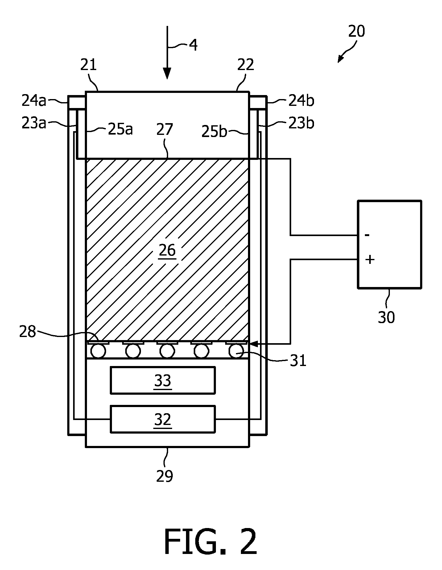
[0009]The invention is based on the idea that, since the radiation reaching the second layer has been partly absorbed by passing the first layer, the intensity of the radiation reaching the second layer has been reduced, diminishing the effect of superimposing of several radiation quanta and, thus, increasing the energy resolution of the energy-resolving detection system.
[0025]In a preferred embodiment, the scintillator material of the second layer is adapted for registering single radiation quanta, in particular single X-ray radiation quanta. It is further preferred that the fast light detection unit is adapted for distinguishing between the light pulses induced by single radiation quanta. This allows detecting single radiation quanta, for example, single X-ray photons, which further improves the energy resolution of the energy-resolving detection system.

Problems solved by technology

This known energy-resolving detection system has the drawback that it can only cope with a limited range of intensities of the radiation.
If the intensity (count rate) is above a certain intensity value, this energy-resolving detection system cannot distinguish between different radiation quanta, in particular X-ray photons, impinging on the energy-resolving detection system, i.e. the detection signals are superimposed signals of several radiation quanta, resulting in a wrong energy measurement leading to a decreased energy resolution of the energy-resolving detection system.
X-ray intensities, which are used in a CT system, are far above the mentioned certain intensity value so that the detection system cannot be operated in a photon-counting mode and that the detection signals generated by the energy-resolving detection system are superimposed signals, which do not provide any energy resolution.

Method used


Image

  • Energy-resolving detection system and imaging system
  • Energy-resolving detection system and imaging system
  • Energy-resolving detection system and imaging system

Examples


Embodiment Construction

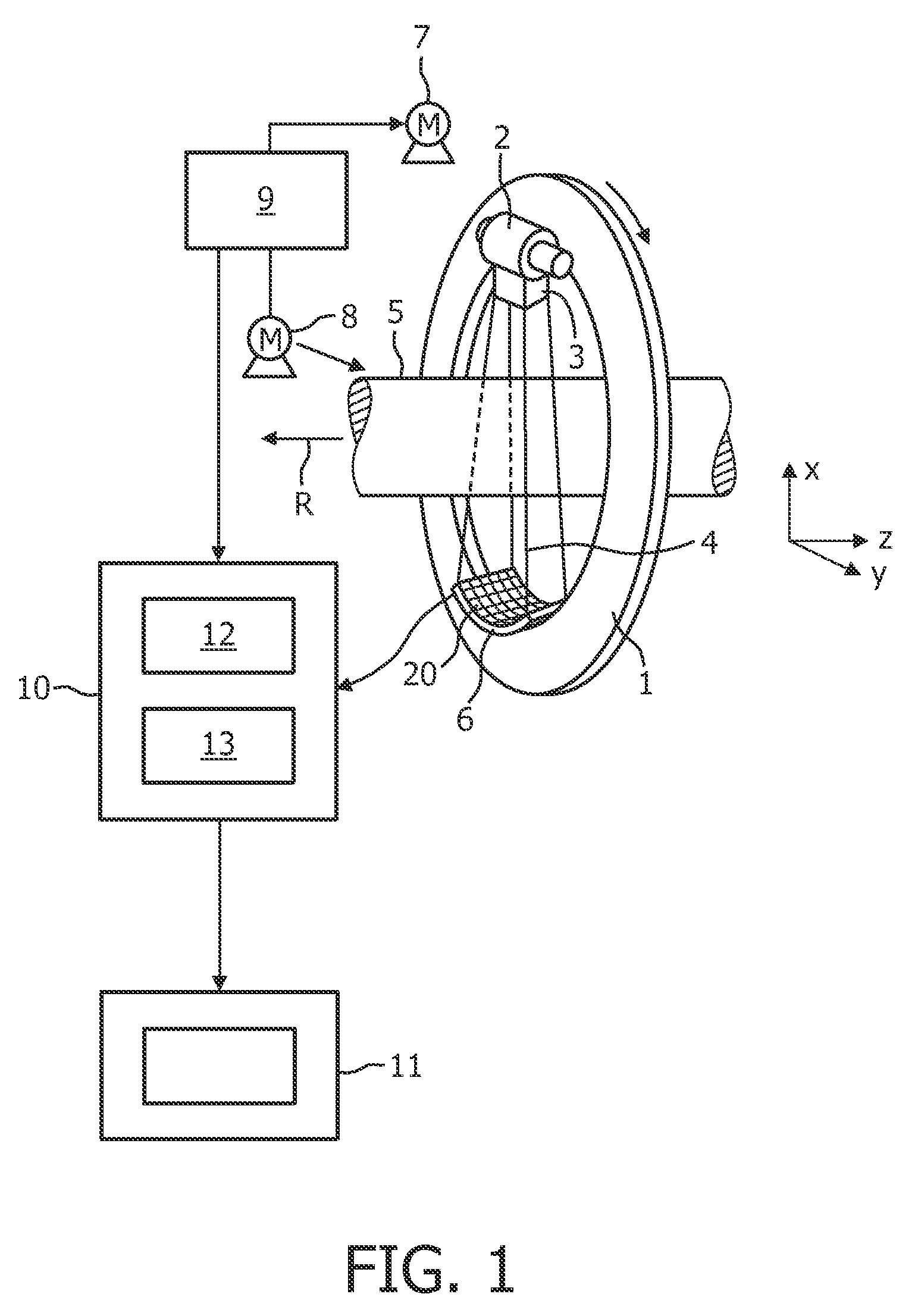
[0045]The imaging system shown in FIG. 1 is a spectral computed tomography system (spectral CT system). The spectral CT system includes a gantry 1 which is capable of rotation about an axis of rotation R which extends parallel to the z direction. A polychromatic radiation source 2, which is in this embodiment an X-ray source 2 emitting polychromatic X-ray radiation (bremsstrahlung spectrum with characteristic lines), is mounted on the gantry 1. The X-ray source 2 is provided with a collimator device 3, which forms in this embodiment a conical radiation beam 4 from the radiation produced by the X-ray source 2. The radiation traverses an object (not shown), such as a patient, in a region of interest in an examination zone 5, which is in this embodiment cylindrical. After having traversed the examination zone 5, the X-ray beam 4 is incident on an energy-resolving detection system 6, which comprises in this embodiment a two-dimensional detection surface. The energy-resolving detection s...


PUM


Abstract

The invention relates to an energy-resolving detection system for detecting radiation (4). The energy-resolving detection system comprises a first layer (21) for absorbing a part of the radiation (4) and a radiation quanta counting unit comprising a second layer (26) for counting radiation quanta of the radiation (4). A read-out unit (29) is coupled with the radiation quanta counting unit for reading out the radiation quanta counting unit. The first layer (21) and second layer (26) are arranged such that the radiation (4), which is incident on the detection system and which reaches the second layer (26), has passed the first layer (21).

Description

FIELD OF THE INVENTION[0001]The invention relates to an energy-resolving detection system for detecting radiation, an imaging system comprising the energy-resolving detection system and a method for producing an energy-resolving detection system.BACKGROUND OF THE INVENTION[0002]Energy-resolving detection systems can, for example, be used for spectral computed tomography (spectral CT), wherein an object, which has to be reconstructed, is illuminated with a spectrum of radiation, in particular a spectrum of X-ray radiation, and wherein the radiation after having passed the object is detected by an energy-resolving detection system, which is adapted for detecting radiation energy-resolved.[0003]V. B. Cajipe et al. disclose in “Multi-Energy X-ray Imaging with Linear CZT Pixel Arrays and Integrated Electronics,” 14th Intl. Workshop on Room-Temperature Semiconductor X-Ray and Gamma-Ray Detectors, Rome, Italy, Oct. 18-22, 2004 an energy-resolving detection system, which uses cadmium zinc t...

Claims


Application Information

Patent Timeline
Patent Type & Authority Applications(United States)
IPC IPC(8): G01T1/36G01T1/20G01T1/24
CPCG01T1/362G01T1/2928
Inventor BAEUMER, CHRISTIANZEITLER, GUENTERHERRMANN, CHRISTOPHSTEADMAN BOOKER, ROGERENGEL, KLAUS JURGEN
Owner KONINKLIJKE PHILIPS ELECTRONICS NV
Learn More