Planar illumination device and liquid crystal display device using the same

a technology of liquid crystal display and illumination device, which is applied in the direction of planar/plate-like light guides, lighting and heating apparatus, instruments, etc., can solve the problems of inability to ensure a sufficient luminance, prone to non-uniform luminance, and difficulty in thinning, so as to improve light utilization efficiency, reduce power consumption, and improve the effect of transmission efficiency of liquid crystal display panel

Active Publication Date: 2010-01-21
PANASONIC CORP
View PDF9 Cites 21 Cited by
  • Summary
  • Abstract
  • Description
  • Claims
  • Application Information

AI Technical Summary

Benefits of technology

[0013]An object of the present invention is to provide a planar illumination device, which realizes a high light utilization efficiency and low power consumption by improving the transmission efficiency of a liquid crystal display panel.
[0015]According to the foregoing structure of the planar illumination device, the liquid crystal display panel is irradiated with the light emitted from the light source unit in such a manner that the polarization direction thereof is brought into substantially coincide with the transmission axis direction of the liquid crystal display panel. With this structure, the transmission efficiency of the liquid crystal display panel can be improved, thereby realizing a light utilization efficiency while reducing power consumption.

Problems solved by technology

However, in order to realize this, direct illumination devices have a problem of being difficult to be thinned and edge light type illumination devices using conventional light sources have a problem of being unable to ensure a sufficient luminance if screens are large.
That is, according to Patent Document 1, since a light is incident on a light guide plate from only one direction, a problem of non-uniform luminance is liable to occur when applied to a large size screen.
A problem of non-uniform color is also liable to occur due to differences in absorption when three color lights, i.e., red, green and blue lights propagate in the light guide plate.
Power consumption thereof tends to increase substantially in proportion to the screen size.
Furthermore, the power consumption of the backlight accounts for the large proportion of the total power consumption of the liquid crystal display device, and the problem of the power consumption has been a curtail issue for the liquid crystal display device.
However, such applications adopting the light-output laser light sources have a drawback in that the required power consumption is larger than that of cathode fluorescent tubes at present, and a reduction in power consumption is therefore a critical issue.
However, there still exists a strong demand for a reduction in power consumption, and with the foregoing conventional methods, the power consumption cannot be reduced to a sufficient level to meet such demands.

Method used


Image

  • Planar illumination device and liquid crystal display device using the same
  • Planar illumination device and liquid crystal display device using the same
  • Planar illumination device and liquid crystal display device using the same

Examples


first embodiment

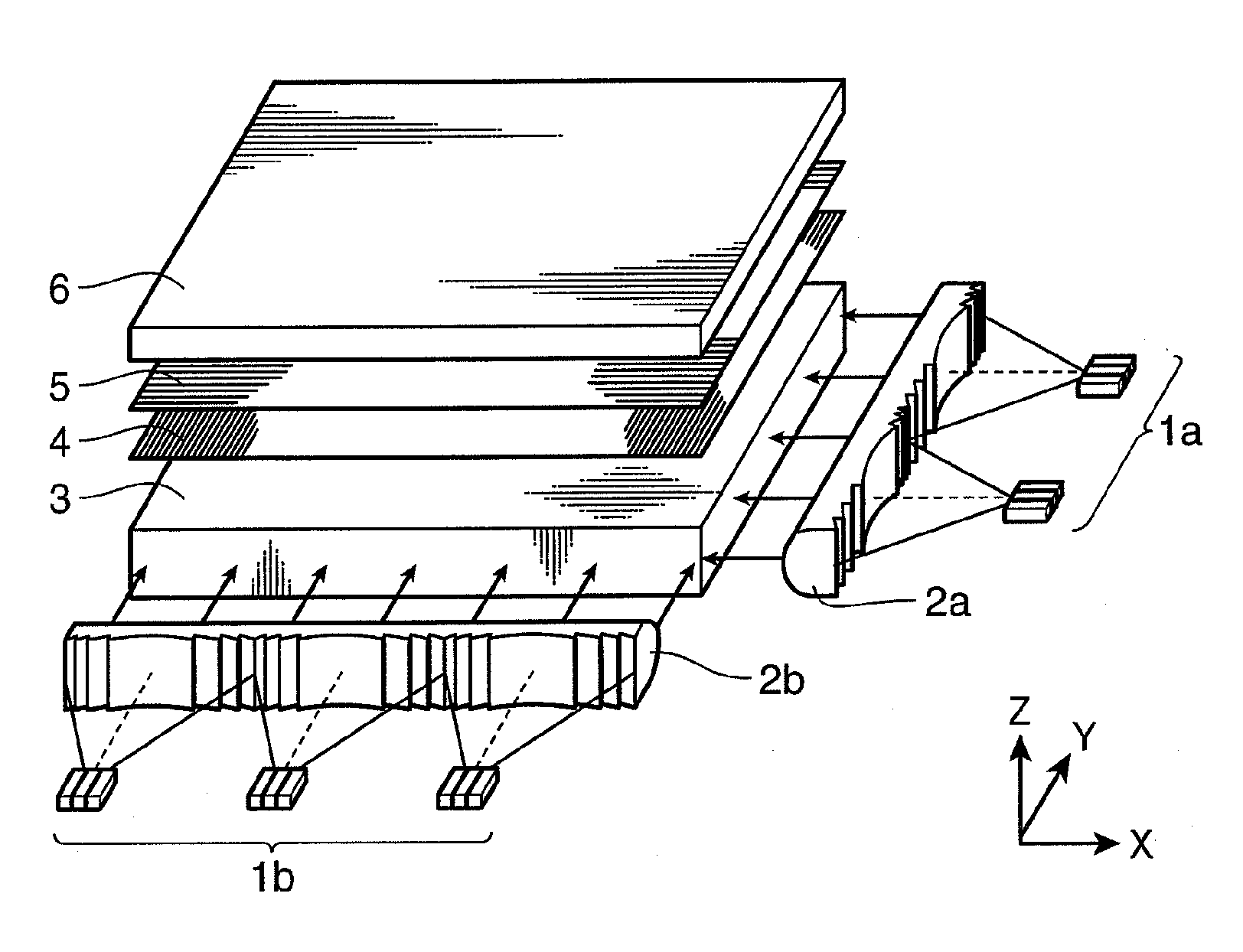
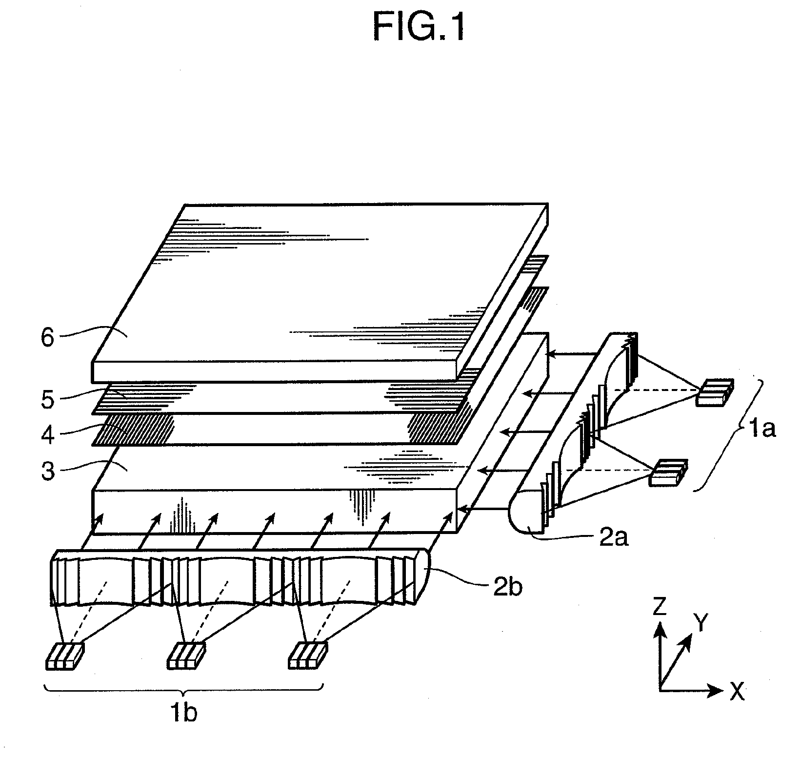
[0033]FIG. 1 is a perspective view showing a schematic structure of a planar illumination device according to the first embodiment of the present invention. FIG. 1 shows a liquid crystal display panel 6 to be illuminated with the planar illumination device of the present embodiment and prism sheets 4, 5 arranged between the planar illumination device of the present embodiment and the liquid crystal display panel 6 in addition to the planar illumination device of the present embodiment.

[0034]As shown in FIG. 1, the planar illumination device according to the present embodiment includes linear light source units 1a and 1b, cylindrical lenses 2a and 2b, and a light guide plate 3. The linear light source unit 1a includes two laser light sources arranged in the Y-direction in FIG. 1, and laser lights emitted from the respective laser light sources are outputted to the cylindrical lens 2a while being converted into linear lights, for example, using cylindrical lenses (not shown). The resp...

second embodiment

[0048]Next, the second embodiment of the present invention is described. In the foregoing first embodiment, the linear light source units 1a and 1b are provided in the outside of the light guide plate 3 as shown in FIG. 1. In the present invention, a light source unit is arranged on the underside of the light guide plate 3 and lights are incident on the light guide plate 3 while being polarized by mirrors or the like. FIGS. 4A and 4B are a rear view and a side view respectively showing a schematic structure of a planar illumination device according to the present embodiment.

[0049]As shown in FIGS. 4A and 4B, the planar illumination device according to the present embodiment includes a light source unit 11, a half wave plate 12, a polarizing beam splitter 13, linearization optical elements 14a and 14b, prisms 15a and 15b and the light guide plate 3. The light source unit 11 combines and outputs lights having aligned polarizations from laser light sources 11a for three primary colors,...

third embodiment

[0052]Next, the third embodiment of the present invention is described. The present embodiment differs from the foregoing second embodiment in that a light emitted from the light source unit 11 is guided to the underside of the light guide plate 3 using an optical fiber 3. FIG. 5 is a rear view showing a schematic structure of a planar illumination device according to the present embodiment.

[0053]As shown in FIG. 5, the planar illumination device according to the present embodiment includes a light source unit 11, collimator lenses 16 and 18, an optical fiber 17, a polarization beam splitter 13, linearization optical elements 14a and 14b, prisms 15a and 15b and a light guide plate.

[0054]In the planar illumination device according to the present embodiment, light from the light source unit 11 is condensed by the collimator lens 16 to be incident on the optical fiber 17 and light emitted from the optical fiber 17 is formed into substantially parallel light by the collimator lens 18 to...


PUM

PropertyMeasurementUnit
transmissionaaaaaaaaaa
sizeaaaaaaaaaa
luminanceaaaaaaaaaa

Abstract

A planar illumination device for illuminating a liquid crystal display panel provided with a polarizing plate on a light incident side, includes: a light source unit for emitting light having a specified polarization direction; and a light irradiating member for deflecting light emitted from the light source unit and irradiating the liquid crystal display panel with the deflected light, wherein the light irradiating member deflects the light emitted from the light source unit such that the polarization direction of the light emitted from the light source unit substantially coincides with a transmission axis direction of the polarizing plate of the liquid crystal display panel.

Description

FIELD OF TECHNOLOGY[0001]The present invention relates to a planar illumination device suitable as a backlight of a thin flat display used in a television set or the like, and a liquid crystal display device using the same.DESCRIPTION OF THE BACKGROUND ART[0002]Conventionally, backlight illumination devices utilizing a cold cathode fluorescent tube have been widely used in liquid crystal display devices using liquid crystal display panels. In recent years, attention has been focused on backlight illumination devices using three color light emitting diodes (LED devices) of red, green and blue lights for the reproduction of more clear and natural color tones, and the development thereof has been vigorously promoted.[0003]A planar illumination device of the lateral light source type so-called edge light type in which light from a light source is incident through a side surface (light incident surface) of a light guide plate and light is emitted from one principal surface (light output ...

Claims


Application Information

Patent Timeline
Patent Type & Authority Applications(United States)
IPC IPC(8): G02F1/1335F21V7/04
CPCG02B6/0025G02B6/003G02F1/133615G02B6/0041G02F1/133603G02B6/0036
Inventor NAGATA, TAKAYUKIITOH, TATSUOYAMAMOTO, KAZUHISA
Owner PANASONIC CORP
Why Eureka
Try Eureka