
Analytical System Comprising An Arrangement For Temporally Variable Spatial Light Modulation And Detection Method Executable Therewith

a spatial light modulation and analytical system technology, applied in the field of analytical systems, can solve the problems of high time expenditure for reading a large array, low sensitivity, and relatively complex optical design, and achieve the effect of reducing the total number of optical components of the system and reducing the system cos

Inactive Publication Date: 2010-01-21
WIKI MAX
View PDF18 Cites 25 Cited by
  • Summary
  • Abstract
  • Description
  • Claims
  • Application Information

AI Technical Summary

Benefits of technology

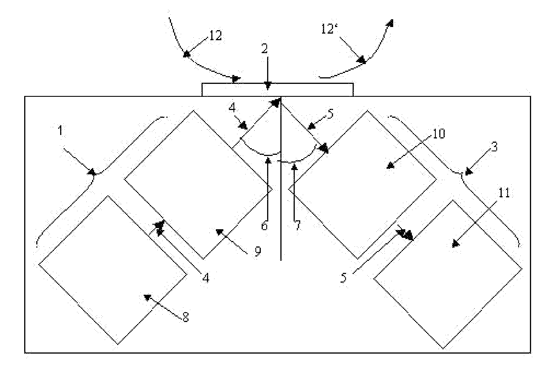
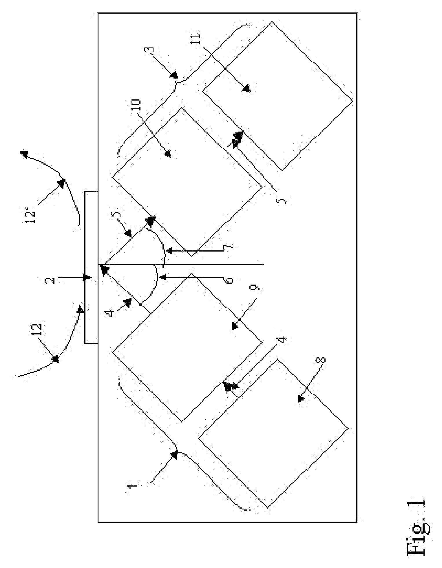
[0022]The freely adjustable geometry of the illuminating pattern on the sensor platform makes it possible to specifically illuminate metering ranges in any arrangement and geometry on the sensor platform and to specifically shadow areas between the metering ranges so that the generation of impairing scatter signals or interference signals from these neighboring areas can be avoided. The illuminating pattern can thereby be varied at a high speed. An extremely rapid optical “scanning” of the entire surface of the sensor platform with limitation of the signal excitation to the metering ranges themselves and the detection of the signals from a plurality of metering ranges is thus made possible in an advantageous manner, wherein the afore-mentioned disadvantages of scan arrangements and methods are avoided at the same time.
[0034]The total number of optical components of the system can be reduced, which leads to a reduction of the system costs: a plurality of diffractive optical elements and masks can be replaced by a single SLM.

Problems solved by technology

The entire array can be illuminated simultaneously by means of a widened excitation light beam, which, however, leads to a relatively low sensitivity, because the portion of diffused light is relatively large and because diffused light or underground fluorescent light from the glass substrate is also generated in the area, which does not contain detection elements, which are immobilized for bonding the analyte.
However, this can lead to a higher expenditure of time for reading a large array and to a relatively complex optical design.
It is a disadvantage of these arrangements, however, that, due to the continuous large-area illumination of the sensor platform, which is not limited to the areas of the metering ranges, in particular signals from the intermediate areas between the metering ranges can lead to an increased basic signal, which is not caused by the presence of an analyte, which, due to the resulting increase of the level of the basic signal, leads to a reduced signal-to-noise ratio and which can thus lead to a reduced sensitivity for the determination of a plurality of analytes as compared to the sensitivity for a single analyte determination in a single metering range with an excitation, which is limited thereto and to a detection on a sensor platform of an otherwise similar technical design.
Furthermore, there is a higher risk of an optical crosstalk of the signals from the different metering ranges in response to a continuous large-area illumination.
In particular in the case of sensor platforms having large dimensions, for example in the format of a standard microtiter plate, extended total times for the signal absorption and possibly also extensive mechanical positioning devices for necessary translations across large traverse paths, combined with very high demands on the positioning accuracy, are to be expected, which can additionally lead to a disadvantageous increase of the system costs.

Method used


Image

  • Analytical System Comprising An Arrangement For Temporally Variable Spatial Light Modulation And Detection Method Executable Therewith
  • Analytical System Comprising An Arrangement For Temporally Variable Spatial Light Modulation And Detection Method Executable Therewith
  • Analytical System Comprising An Arrangement For Temporally Variable Spatial Light Modulation And Detection Method Executable Therewith

Examples


example 1

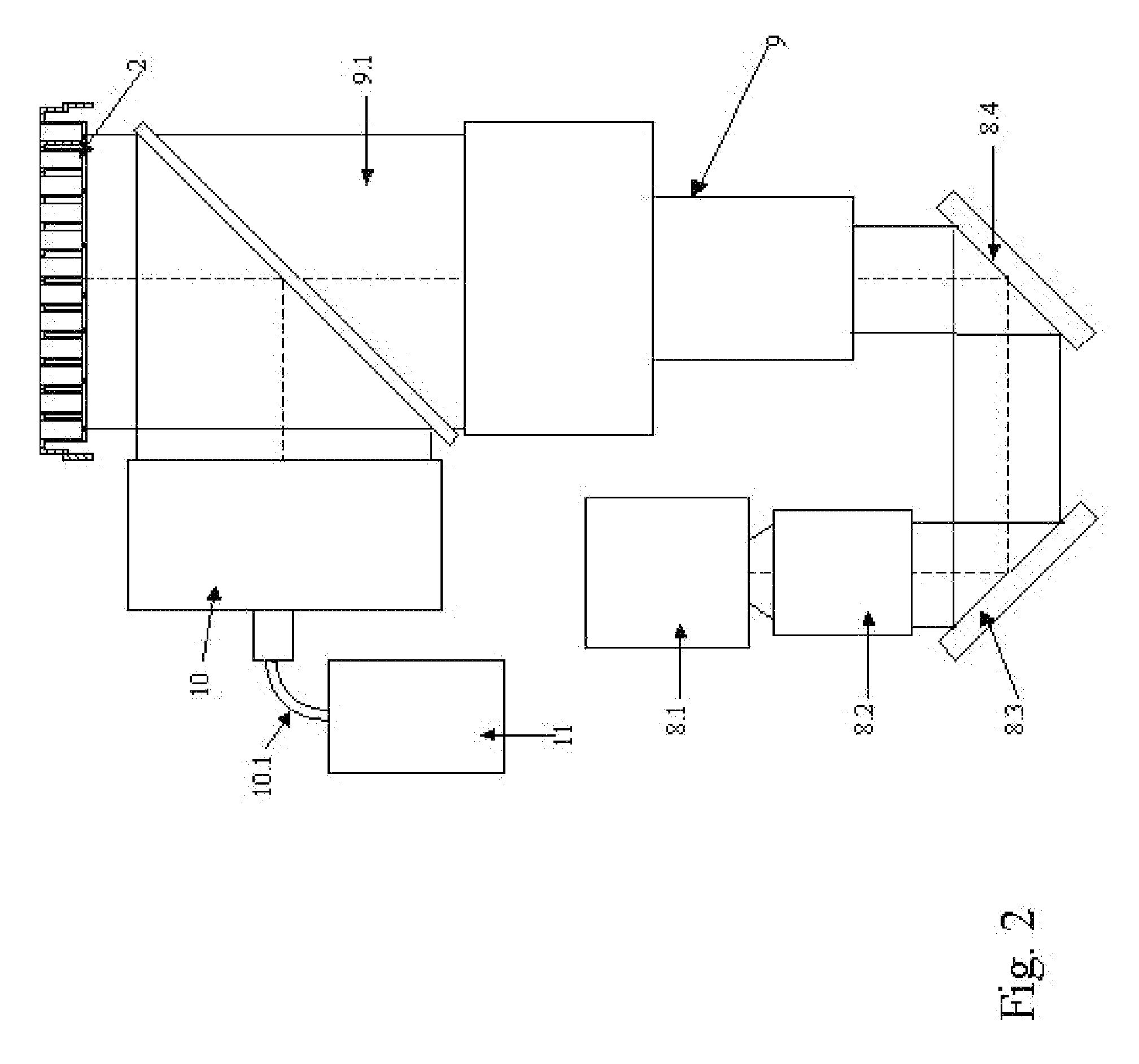
[0124]The assembly of the analytical system corresponds to the embodiment according to FIG. 4, that is, to the arrangement of the illuminating system and of the detection system on opposite sides of the sensor platform and detection of the transmitted light portion. According to a preferred embodiment of such an arrangement, the illuminating system 1 comprises a commercial projection system comprising light-emitting diodes (LEDs) as light sources. A projection system of type FF1 (Toshiba, Taiwan), for example, is suitable for this purpose. FIG. 12 shows the emission spectrum of this projector in response to a simultaneous operation of all three LED light sources. The used blue, green and red LEDs have central emission wavelengths of 460 nm, 520 nm and 627 nm, respectively, and a spectral emission bandwidth of typically 20 nm to 40 nm. The following examples mainly use the red light source, wherein it goes without saying that light sources of other emission spectrums, for example com...

example 2

[0134]The assembly of the analytical system corresponds to the embodiment according to FIG. 3, that is, to the arrangement of the illuminating system and of the detection system on the same side of the sensor platform and detection in the direction of the reflected light portion. According to a preferred embodiment of such an arrangement, the illuminating system 1 comprises a commercial projection system comprising light-emitting diodes (LEDs) as light courses. A projection system of type FF1 (Toshiba, Taiwan), for example, is suitable for this purpose. FIG. 11 shows the emission spectrum of this projection system in response to a simultaneous operation of all three LED light sources. The used blue, green and red LEDs have central emission wavelengths of 460 nm, 520 mm and 627 nm, respectively, and a spectral emission bandwidth of typically 20 nm to 40 nm. The light of the LEDs is homogenized by means of a “light tunnel” and is directed onto a Digital Mirror Device (DMD) as SLM 4. T...


PUM

PropertyMeasurementUnit
response timeaaaaaaaaaa
frequencyaaaaaaaaaa
frequencyaaaaaaaaaa

Abstract

The invention relates to an analytical system and to a method performed therewith for generating and metering optical signals and / or the variations thereof from metering ranges, which are arranged in a one-dimensional or two-dimensional array on a substantially optically transparent sensor platform (2), at least comprisingan optical system comprising an illuminating system (1) for illuminating metering ranges on the sensor platform (2) and a detection system (3) comprising at least one detection unit (11) for detecting signals from the metering ranges on the sensor platform (11) the direction of the transmission or reflection of the illuminating light in a spectral range, which comprises the spectral range of the illuminating light, anda sensor platform (2), which can be inserted into the optical system, comprising metering ranges, which are arranged thereon in a one-dimensional or a two-dimensional array,characterized in that the illuminating system (1) comprises an arrangement (8.4) identified as “SLM” for the temporally rapidly variable spatial light modulation, by means of which in the operating state, illuminating patterns of a freely selectable and rapidly variable geometry, which can be determined by the settings of the SLM (8.4), can be generated on the sensor platform (2) from an illuminating light (4), which enters into this SLM (8.4) and which comprises a substantially homogenous intensity distribution in the cross section of the illuminating light at right angle to its direction of expansion.The invention also relates to the use of the analytical system according to the invention and to the methods according to the invention carried out therewith.

Description

TECHNICAL FIELD[0001]The instant invention relates to an analytical system and to a method executable therewith, for generating and metering optical signals from metering ranges, which are arranged in a one-dimensional or two-dimensional array on a fixed support as metering platform, which will be identified hereinbelow as sensor platform. Such an analytical system and method can be used, for example, for analyzing specimen with reference to biologically, biochemically or synthetically produced substances as analytes contained therein. The invention relates in particular to such a system and method, which is suitable to analyze an individual specimen with reference to a plurality of analytes and / or a plurality of specimens with reference to one or a plurality of analytes on a common sensor platform at the same time. The analytical system according to the invention is thereby suitable for refractive metering methods.STATE OF THE ART[0002]In the past, numerous embodiments of so-called...

Claims


Application Information

Patent Timeline
Patent Type & Authority Applications(United States)
IPC IPC(8): G01N21/55G01N21/00
CPCG01N21/253G01N21/552G02B21/34G02B21/06G01N21/7703
Inventor WIKI, MAX
Owner WIKI MAX
Learn More