Microscope

a superresolution, microscope technology, applied in the field of microscopes, can solve the problems of superresolution microscope, inability to essentially expect more spatial resolution, inability to accurately identify the chemical composition of samples, etc., to achieve the effect of improving the convenience of use, reducing wave aberration, and high image formation performan

Inactive Publication Date: 2010-01-21
OLYMPUS CORP
View PDF3 Cites 25 Cited by
  • Summary
  • Abstract
  • Description
  • Claims
  • Application Information

AI Technical Summary

Benefits of technology

[0078]Moreover, the space modulating element and the wavelength-selecting element may be provided in a lens barrel of the microscope objective lens. If employing such a construction, by exchanging a microscope objective lens only, a super-resolving function can be given to a commercially available laser scanning type microscopy system without modifying its configuration, thereby improving its convenience.
[0079]Particularly, if the space modulating element and the wavelength selecting element are arranged at the pupil position of the microscope objective lens, there is less wave aberration even when the pump light and the erase light are spatially scanned so that the high image formation performance can be held with a wide field of view particularly without disturbing the light collection shapes of the erase light which might exert an influence on the super-resolving microscope faculty.
[0080]Moreover, the super-resolving microscope according to the invention is widely applicable to the observation of illuminant materials exhibiting the fluorescence suppression effect, For example, the invention is applicable to observations of samples of fluorescent molecules consisting of organic dye molecules such as rhodamine 6G realizing the fluorescence suppression effect having two or more excited quantum states, semiconductor quantum dots such as Csd or ZnO, fluorescent complex molecules such as tri (8-quinolinol) aluminum, fluorescence protein exhibiting the photochromic characteristics such as FP595GFP, and the like.

Problems solved by technology

At this moment, even with the illumination of single wavelength of the prior art, to some extent it is possible to observe absorption images or fluorescent images of particular molecules, but it is impossible to accurately identify the chemical compositions of the sample, because regions of wavelengths of absorption bands in some molecules are generally overlapped.
In other words, with the prior art scanning laser microscopes and the like, laser beams are focused by collecting lens into microbeams by means of which a sample is scanned, on that occasion the size of the microbeams provides a limitation of diffraction determined by numerical apertures of the collecting lens and wavelength so that any more spatial resolution cannot be essentially expected.
According to the experimental investigation of the inventors of the present application, however, the super-resolving microscope hitherto proposed have problems described below to be solved, particularly in performance of image formation and assembling of microscopes.
Consequently, the peak position of the pump light would shift toward the periphery of the erase light on the focal plane so that the fluorescence in the whole focused region of the pump light is suppressed, thereby worryingly causing deterioration of resolution and S / N ratio.

Method used


Image

  • Microscope
  • Microscope
  • Microscope

Examples


first embodiment

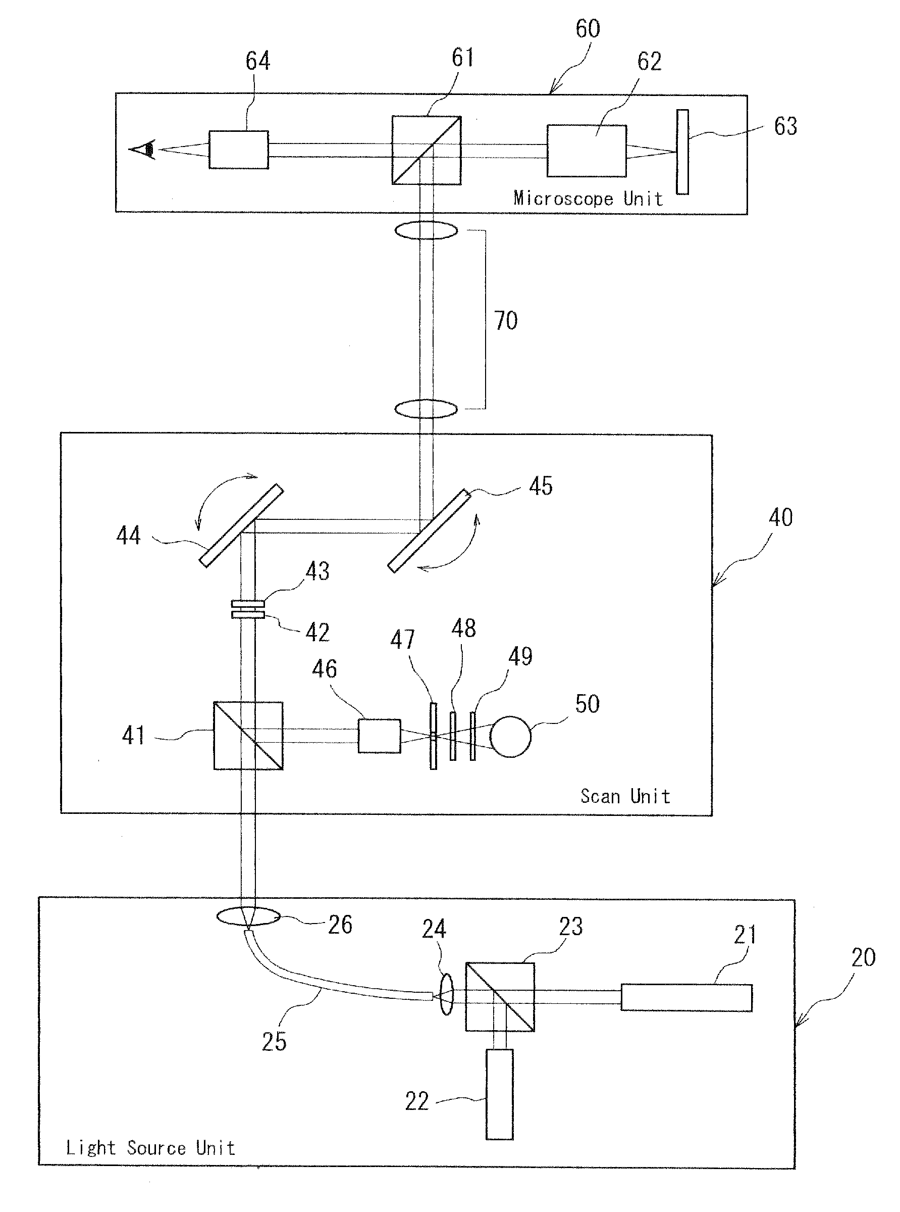
[0099]FIG. 7 is a block diagram of main parts of the optical system of the super-resolving microscope according to the first embodiment of the invention. This super-resolving microscope mainly comprises three independent units, that is, a light source unit 20, a scan unit 40, and a microscope unit 60. The scan unit 40 and the microscope unit 60 are optically combined with each other through a pupil projection lens system 70.

[0100]In the light source unit 20, pump light output from a pump light source 21 and erase light output from an erase light source 22 are combined with each other at dichroic prisms 23 and thereafter the combined lights are coaxially induced into the same single mode fiber 25 through a fiber collecting lens 24 so that the combined lights are output from the outlet opening of the single mode fiber 25 as complete spherical waves with equalized emission solid angles. The output lights are converted to plane waves at a fiber collimator lens 26 so as to be fed into th...

second embodiment

[0110]FIG. 8 is a block diagram of main parts of the optical system of the super-resolving microscope according to the second embodiment. This super-resolving microscope is different in the constitution of the light source unit 20 from the super-resolving microscope shown in FIG. 7.

[0111]In other word, according to the present embodiment, the pump light and the erase light are coaxially combined without using any optical fiber and thereafter the erase light is modulated in phase. For this purpose, the pump light emitted from the pump light source 21 is conducted to angle adjusting mirrors 31a and 31b where the angles of the pump light in two dimensional directions are adjusted, and further conducted to a beam divergent angle-adjusting lens 32 where divergent angles of the pump light are adjusted. Thereafter, the pump light is caused to be incident to dichroic prisms 33. Similarly, the erase light emitted from the erase light source 22 is conducted to angle adjusting mirrors 34a and ...

third embodiment

[0114]FIG. 9 is a cross-sectional view of a substantial part of the optical system of the super-resolving microscope according to the third embodiment. The configuration of the present embodiment lies in a wavelength selecting element 42 and a space-modulating element 43 arranged in a lens barrel 62a of a microscope objective lens 62 in the configuration of the first or second embodiment.

[0115]In more detail, in the lens barrel 62a of the microscope objective lens 62 the wavelength selecting element 42 and the space-modulating element 43 are arranged on the side of image of the microscope objective lens system 62b (on the incident side). Moreover, the galvano mirrors 44 and 45 are arranged so as to be located on both sides of the conjugate pupil surface of the microscope objective lens 62 projected by the pupil projection lens system 70 (this arrangement is not shown).

[0116]According to the present embodiment, in the same manner of the embodiments described above, a high image forma...


PUM


Abstract

A microscope for observing a sample containing a substance having at least two excited quantum states includes a pump light source 21 for emitting pump light, an erase light source 22 for emitting erase light, a light combining section 23 to 26 for coaxially combining the pump light and the erase light, a light collecting section 62 for collecting the combined lights, a scanning section 44 and 45 for scanning the sample with the combined lights, a detecting section 50 for detecting photoresponsive signals generated from the sample, a wavelength selecting element 42 arranged in the light path of the combined lights and provided with an erase light selecting region having a high wavelength selectivity for the erase light and with a pump light selecting region having a high wavelength selectivity for the pump light, and a space modulating element 43 arranged in the light path of the combined lights for spatially modulating the erase light corresponding to the erase light selecting region of the wavelength selecting element.

Description

CROSS-REFERENCE OF RELATED APPLICATION[0001]The present application is claiming the priority based on the Japanese Patent Application No. 2006-232,115 filed on Aug. 29, 2006. The whole disclosure of the original application is incorporated herein for reference.TECHNICAL FIELD[0002]This invention relates to a microscope, and more particularly to a highly efficient and highly functional super-resolving microscope enabling a high spatial-resolution by irradiating a stained sample with lights of wavelengths from laser sources of high functionality.BACKGROUND ART[0003]The technique of optical microscopes has an old history during which various types of microscopes have been developed. In recent years, moreover, as peripheral technologies such as laser technology and electronic imaging technology have been advanced, even higher-performance microscopic systems have been developed.[0004]In such a background, high-performance microscopes have been proposed which use the double resonance abso...

Claims


Application Information

Patent Timeline
Patent Type & Authority Applications(United States)
IPC IPC(8): G02B21/06
CPCG01N21/6458G01N2021/6415G01N2201/06113G01N2201/104G01N2201/1053G02B2207/113G02B5/3083G02B21/002G02B21/16G02B26/06G02B5/20
Inventor IKETAKI, YOSHINORI
Owner OLYMPUS CORP
Why Eureka
Try Eureka