Power generating plant

a power generation plant and power technology, applied in the direction of combustible gas purification/modification, combustible gas production, fuel cells of fused electrolyte, etc., can solve the problem of not having gasification coal and resulting gas as fuel technologies

a power generation plant and power technology, applied in the direction of combustible gas purification/modification, combustible gas production, fuel cells of fused electrolyte, etc., can solve the problem of not having gasification coal and resulting gas as fuel technologies

US20100015486A1Inactive Publication Date: 2010-01-21CENTRAL RESEARCH INSTITUTE OF ELECTRIC POWER INDUSTRY

Image

  • Power generating plant
  • Power generating plant
  • Power generating plant

Examples


Embodiment Construction

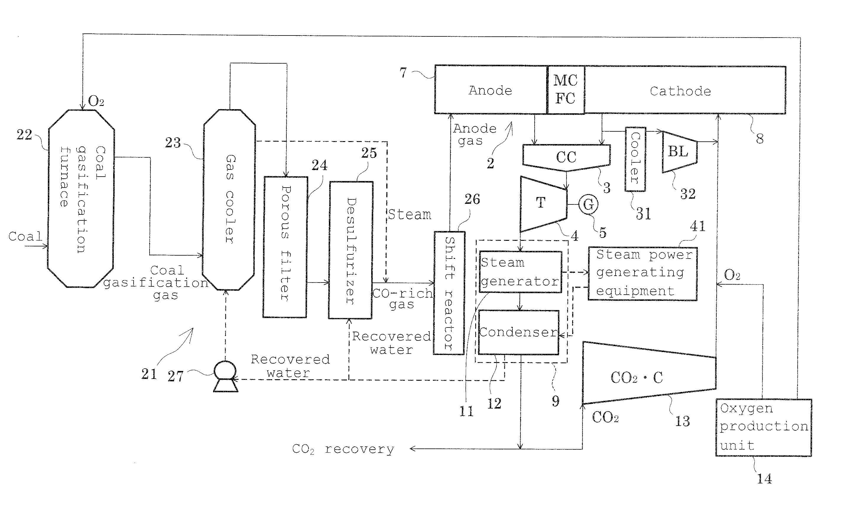
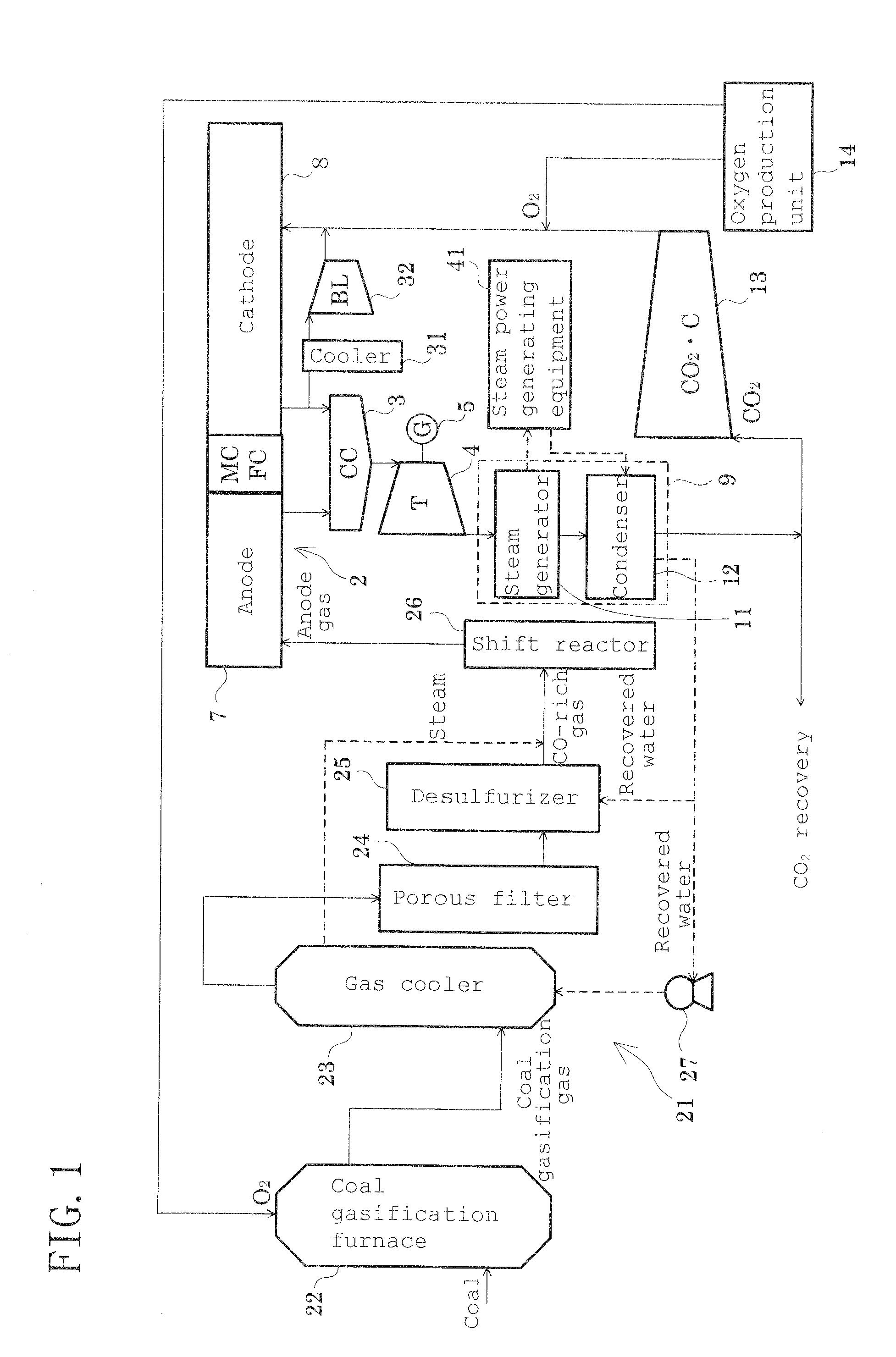
[0040]In the power generating plant according to the embodiment of the present invention, a coal gasification fuel gas obtained by burning coal in a coal gasification furnace is desulfurized to form a CO gas-containing gas substantially containing a CO gas. The CO gas-containing gas is converted into H2 and CO2 by a chemical reaction in a shift reaction means to obtain an anode gas heated to a desired temperature by an exothermic reaction. This anode gas is supplied to an anode of a molten carbonate fuel cell (MCFC). A cathode of the MCFC is supplied with pure oxygen and a CO2 gas as a cathode gas.

[0041]The cathode gas supplied to the cathode is a gas containing pure oxygen and a CO2 gas. It is preferred for this cathode gas to be operated in a minimum amount of use (a minimum amount necessary for a power generating reaction) in order to reduce a loss in oxygen production power or the like, cut down on the power of a cathode circulating blower, and suppress gas leakage caused by mai...


PUM

PropertyMeasurementUnit
operating current densityaaaaaaaaaa
unit cell voltageaaaaaaaaaa
temperatureaaaaaaaaaa

Abstract

Coal is reacted in a furnace 22 to obtain a coal gasification gas. The coal gasification gas is cooled by a gas cooler 23, passed through a porous filter 24, and desulfurized by a desulfurizer 25 to produce a CO-containing gas as an anode. The CO gas-containing gas is subjected to an exothermic reaction in a shift reactor 26 to form H2 and CO2, and the anode gas containing H2 is supplied to an anode 7 of MCFC 2. Thus, in the absence of an extra heat source and a heat exchange source, a desired anode gas is obtained from the coal gasification gas, and with heat buildup of the MCFC 2 being inhibited and its performance being maintained, reduction of CO2 is taken into consideration. A power generating plant equipped with the MCFC 2 capable of using a coal gasification fuel substantially containing a CO gas is thus achieved.

Description

TECHNICAL FIELD [0001]This invention relates to a power generating plant equipped with a molten carbonate fuel cell which obtains electric power by an electrochemical reaction between hydrogen and oxygen.BACKGROUND ART [0002]A molten carbonate fuel cell (MCFC), which obtains electric power by an electrochemical reaction between hydrogen and oxygen, is constituted by interposing an electrolyte (carbonate) between a fuel electrode (anode), for example, formed from a nickel porous material and an air electrode (cathode), for example, formed from a nickel oxide porous material. In the MCFC, hydrogen (H2) obtained from a fuel, such as a natural gas, is supplied to the anode, while air (O2) and carbon dioxide (CO2) are supplied to the cathode, whereupon power generation is performed by an electrochemical reaction between H2 and O2. The MCFC is characterized, for example, by having a high efficiency because of its operation at high temperatures, and by minimally affecting the environment b...

Claims


Application Information

Patent Timeline
21 Jan 2010
Publication
US20100015486A1
IPC
H01M8/04
CPC
H01M8/04022; Y02E20/18; H01M8/04126; H01M8/04141; H01M8/04164; H01M8/04268; H01M8/0618; H01M8/0643
Inventors
YOSHIBA, FUMIHIKO