Signal decomposition methods and apparatus for multi-mode transmitters

a multi-mode communication and decomposition method technology, applied in the field of signal decomposition methods and apparatus for multi-mode communication transmitters, can solve the problems of lack of power efficiency, linear pas configured to operate at reduced drive levels, and not very power efficient, so as to reduce the bandwidth of power supply signals, reduce signal bandwidths, and ease the effect of design requirements

Inactive Publication Date: 2010-01-21
PANASONIC CORP
View PDF25 Cites 8 Cited by
  • Summary
  • Abstract
  • Description
  • Claims
  • Application Information

AI Technical Summary

Benefits of technology

[0014]According to another aspect of the invention, the signal decomposition process performed by the signal decomposer includes filtering the amplitude information determined to exceed the predetermined amplitude threshold in the process of forming the first modulation signal. In an alternative embodiment, the signal decomposition process also or alternatively includes filtering signals representing the amplitude information falling below the predetermined amplitude threshold in the process of forming the second modulation signal. Including filtering in the signal decomposition process has the effect of reducing the bandwidth of the power supply signal applied to the power supply port of the multi-mode communications transmitter's PA and / or the bandwidth of the modulated RF signal applied to the RF input port of the PA to a greater extent than is possible by application of ERR alone.
[0015]The reduction of signal bandwidths achieved by the signal decomposition methods and apparatus of the present invention eases the design requirements of the electrical components needed to process and generate the power supply signal and modulated RF signal applied to the power supply and RF input ports, respectively, of the multi-mode communications transmitter's PA. The reduction in signal bandwidths also makes the multi-mode communications transmitter more forgiving to gain and delay mismatches between the signals applied to the power supply and RF input ports of the PA, compared to conventional polar modulation transmitters.

Problems solved by technology

However, a significant limitation is that it is not very power efficient, particularly for communication technologies that employ nonconstant-envelope signals, such as orthogonal frequency division multiplexing (OFDM), and other existing or soon-to-be deployed cellular technologies, such as W-CDMA, High-Speed Packet Access (HSPA) and Long Term Evolution (LTE) communication technologies.
Unfortunately, linear PAs configured to operate at reduced drive levels are not very power efficient.
This lack of power efficiency is a major concern, particularly in battery-powered applications such as, for example, cellular handsets.
First, converting the I and Q signals from rectangular to polar-coordinates often results in substantial bandwidth expansion.
Nonconstant-envelope modulation formats that have signal trajectories which pass through, or close to, the origin in the I-Q signal plane result in the most severe bandwidth expansion.
Not only are such rapid changes in phase difficult to digitally process, they are also difficult to translate to RF.
For example, in the phase path, the phase modulator 206, which is responsible for modulating the phase component signal θ onto the RF carrier signal, is capable of providing a linear response only over a narrowly-defined frequency range and, therefore, is unable to react to abrupt changes in the phase of the phase component signal θ. Bandwidth expansion of signals in the amplitude path can also be problematic.
Given that the switching transistors in state-of-the-art switch-mode converters can only be switched up to a maximum of about 5 MHz, the bandwidth of the amplitude component signal ρ is often a problem that must be addressed.
Another drawback of the polar modulation transmitter 200 involves the timing of the amplitude and phase component signals ρ and θ. Because the amplitude and phase component signals ρ and θ are processed in different paths using different components and at different processing rates, a delay mismatch typically arises between the signals at the RF input and supply ports of the PA 208.
This delay mismatch results in spectral regrowth, a highly undesirable condition that impairs the ability of the polar modulation transmitter 200 to comply with out-of-band noise limitation standards.

Method used


Image

  • Signal decomposition methods and apparatus for multi-mode transmitters
  • Signal decomposition methods and apparatus for multi-mode transmitters
  • Signal decomposition methods and apparatus for multi-mode transmitters

Examples


Embodiment Construction

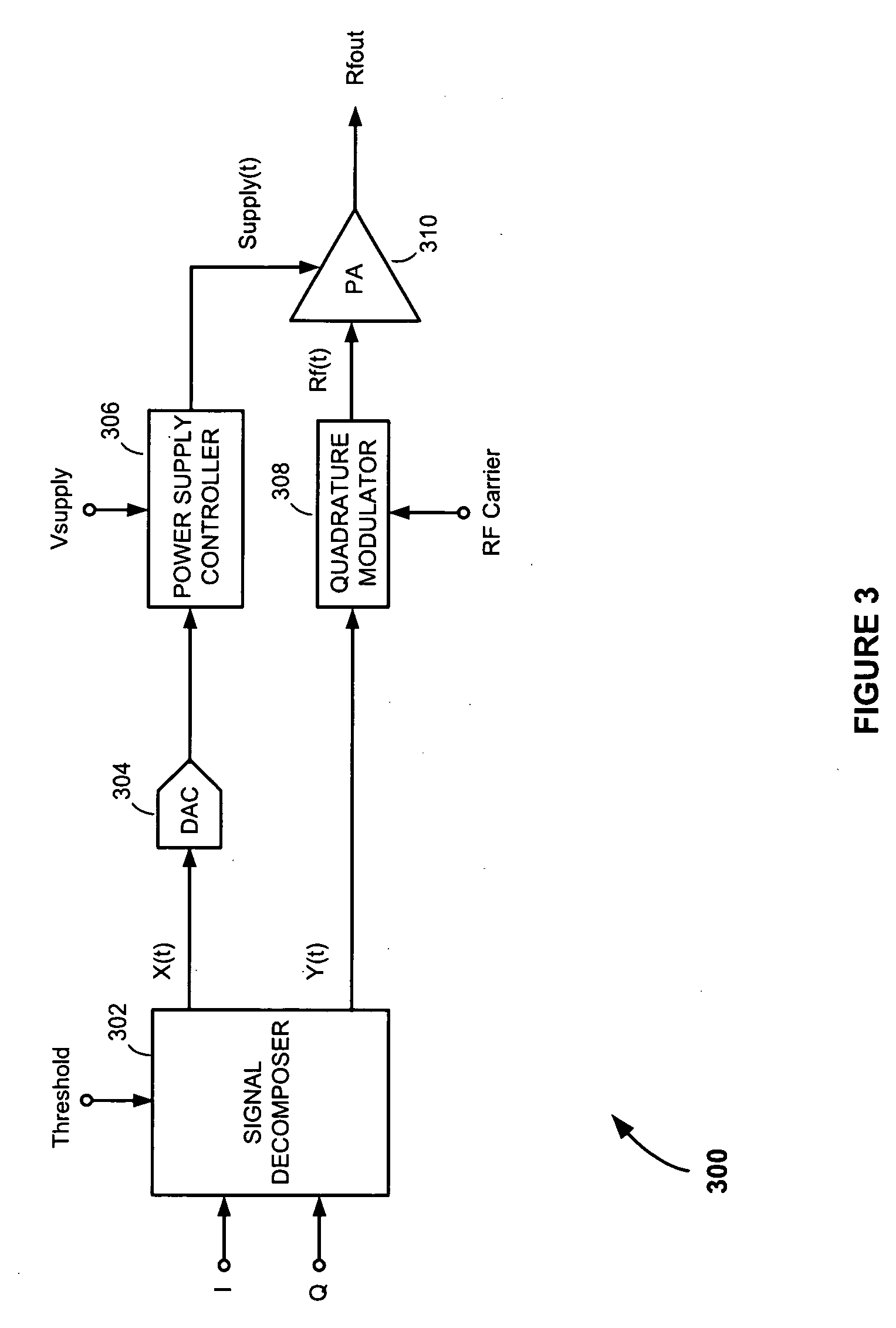
[0028]Referring to FIG. 3, there is shown a multi-mode communications transmitter 300, according to an embodiment of the present invention. The multi-mode communications transmitter 300 comprises a signal decomposer 302; a first modulation path including a digital-to-analog converter (DAC) 304 and power supply controller 306; a second modulation path including a quadrature modulator 308; and a power amplifier (PA) 310.

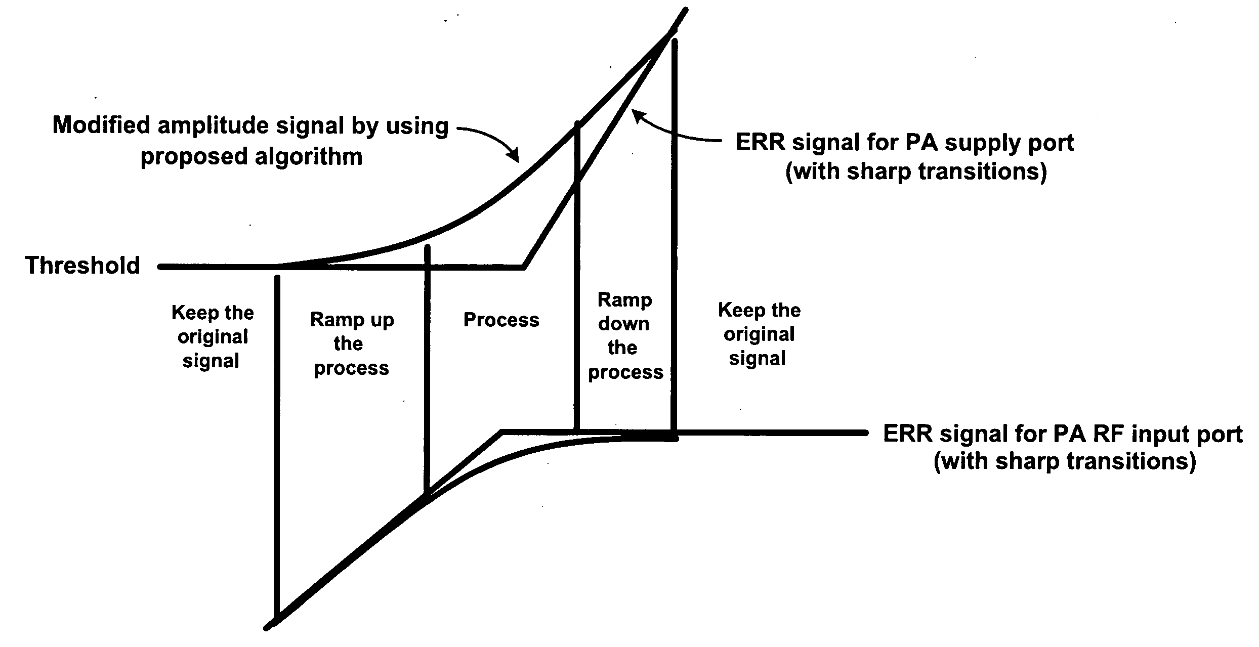
[0029]The signal decomposer 302 operates to convert in-phase (I) and quadrature phase (Q) digital baseband signals to polar-coordinate digital amplitude and phase component signals Am(t)=√{square root over (I2+Q2)} and Pm(t)=tan−1(Q / I), which the signal decomposer 302 then decomposes into first and second digital modulation signals X(t) and Y(t) for the first and second modulation paths. As explained below, the decomposition of the amplitude and phase component signals Am(t) and Pm(t) involves distributing the amplitude information represented in the amplitude componen...


PUM


Abstract

A multi-mode communications transmitter includes a signal decomposer that converts rectangular-coordinate in-channel and quadrature channel signals into polar-coordinate amplitude and angle component signals and form therefrom first and second modulation signals. The signal decomposition process performed by the signal decomposer combines envelope-reduction and restoration (ERR) with filtering to reduce the bandwidths of the first and second modulation signals compared to the bandwidths of the unmodified amplitude and angle component signals. The reduction in signal bandwidths eases the design requirements of the electrical components needed to process and generate the signals applied to the power supply and radio frequency (RF) input ports of the multi-mode communications transmitter's power amplifier (PA). It also makes the multi-mode communications transmitter more forgiving to gain and delay mismatches between the signals applied to the power supply and RF input ports of the PA, compared to conventional polar modulation transmitters.

Description

FIELD OF THE INVENTION[0001]The present invention relates to communications transmitters. More specifically, the present invention relates to methods and apparatus for reducing signal bandwidths in multi-mode communications transmitters.BACKGROUND OF THE INVENTION[0002]Conventional communications transmitters employ a quadrature modulator to modulate information to be transmitted, such as voice or data, onto a radio frequency (RF) carrier signal that is capable of being transmitted through the atmosphere to a remote receiver.[0003]FIG. 1 is a simplified drawing of a conventional quadrature-modulator-based transmitter 100. The quadrature-modulator-based transmitter 100 comprises a quadrature modulator 102 and a power amplifier (PA) 104. The quadrature modulator 102 includes in-phase (I) and quadrature phase (Q) mixers 106 and 108, a local oscillator (LO) 110, a ninety-degree phase shifter 112 and a summer 114.[0004]The I mixer 106 operates to modulate an I signal onto a radio frequen...

Claims


Application Information

Patent Timeline
Patent Type & Authority Applications(United States)
IPC IPC(8): H04B1/66
CPCH04B1/66
Inventor LIANG, PAUL CHENG-POTAKINAMI, KOJI
Owner PANASONIC CORP
Why Eureka
Try Eureka