Light-emitting apparatus with shaped wavelength converter

a technology of light-emitting apparatus and wavelength converter, which is applied in the direction of electrical apparatus, semiconductor devices, instruments, etc., can solve the problems of not being able to use in étendue critical applications, not being able to use light in the application of light-emitting apparatus, and being unable to achieve the effect of enhancing the light output of the luminescent ceramic body

Active Publication Date: 2010-01-28
LUMILEDS
View PDF10 Cites 27 Cited by
  • Summary
  • Abstract
  • Description
  • Claims
  • Application Information

AI Technical Summary

Benefits of technology

[0004]It is an object of the present invention to provide a light-emitting apparatus of the kind set forth, in which light output from the luminescent ceramic body is enhanced. This object is achieved with the light-emitting apparatus according to the invention as defined in claim 1. A light-emitting apparatus comprising a semiconductor light emitting device comprising a light-emitting layer disposed between an n-type region and a p-type region, a transparent ceramic body comprising a wavelength converting material positioned in light receiving relationship to the semiconductor device, the ceramic body further having a bottom surface facing towards the semiconductor device, characterized in that the ceramic body has at least one side surface at an oblique angle with respect to said bottom surface in order to unlock waveguide modes from said ceramic body.

Problems solved by technology

This is a considerable drawback, because the primary light transmitted and the secondary light generated by the luminescent ceramic body can be emitted from the body only within the escape cones extending from all body surfaces.
This light is not available for use in the application of the light-emitting apparatus.
This unavailability is a clear disadvantage both for étendue critical applications (in which the brightness of the top surface of the ceramic body is of importance) as well as for lumen critical applications (in which the total flux emitted by the ceramic body is of importance).
An additional disadvantage of the prior art is that a considerable amount (up to 80% for rectangular bodies) of the light emitted by the transparent luminescent ceramic body is emitted through the side surfaces and therefore not available for use in étendue critical applications.

Method used


Image

  • Light-emitting apparatus with shaped wavelength converter
  • Light-emitting apparatus with shaped wavelength converter
  • Light-emitting apparatus with shaped wavelength converter

Examples


Embodiment Construction

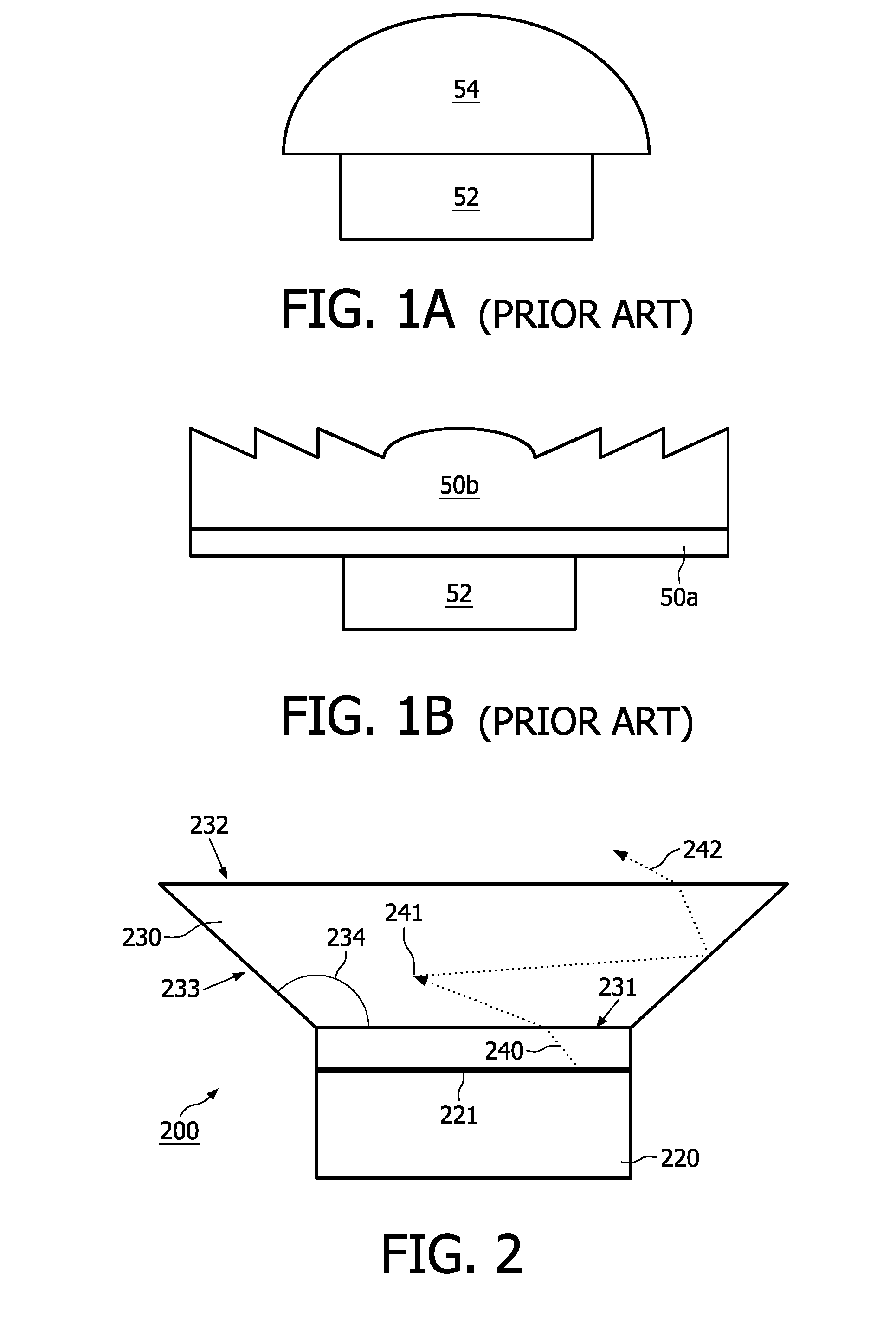
[0024]FIGS. 1A and 1B show two examples of a light-emitting apparatus comprising a semiconductor light-emitting device 52 and a ceramic wavelength conversion body 54, 50a, 50b as known from US2005 / 0269582. In FIG. 1A the ceramic wavelength converting body 54 is shaped to form a dome lens. In FIG. 1B a second ceramic wavelength converting body 50b is shaped to form a Fresnel lens and located on top of a first rectangular ceramic wavelength converting body 50a. The lens shape of the body 54, 50b in the prior art should avoid total internal reflection (TIR) at the interface between the high index of refraction body and the low index of refraction air. The TIR is avoided (or at least minimized) by shaping the lens 54 with a radius of curvature considerably larger than the light-emitting device 52. It is clear, however, that in both embodiments of FIG. 1 TIR still occurs—and consequently locking of light in wave guide modes—even at the shaped surfaces of the ceramic wavelength conversion...


PUM

PropertyMeasurementUnit
oblique angleaaaaaaaaaa

Abstract

Proposed is a light-emitting apparatus 200,300,400, comprising a semiconductor light emitting device 220,320,420 and a transparent ceramic body 230,330,430 comprising a wavelength converting material positioned in light receiving relationship to the semiconductor device. The light-emitting apparatus is characterized in that the side surfaces 233,333,433 of the ceramic body 230,330,430 are at an oblique angle 234,334,434 relative its bottom surface 231,331,431. This is especially advantageous to unlock the wave-guide modes inside the body 230,330,430. Consequently the total flux emitted from the light-emitting apparatus 200,300,400 can be enhanced considerably. Alternatively, the brightness of the top surface 232,332,432 of the ceramic body 230,330,430 can be enhanced considerably.

Description

FIELD OF THE INVENTION[0001]The invention relates to a light-emitting apparatus comprising a semiconductor light-emitting device and a ceramic wavelength conversion body. Such light-emitting apparatuses are well known and used in particular as light sources in indicators, display backlighting units, automotive (head-)lamps and general-purpose illuminators.BACKGROUND OF THE INVENTION[0002]An embodiment of a light-emitting apparatus of the kind set forth is known from US2005 / 0269582. That document discloses a semiconductor device comprising a light-emitting layer disposed between an n-type and a p-type region in combination with a ceramic body, which is disposed in a path of the light emitted by the light-emitting layer. The ceramic body is composed of (or includes) a wavelength converting material, such as a phosphor. Typically these ceramic materials are based on Yttrium Aluminum Garnet (YAG), Yttrium Aluminum Silicon Oxo-Nitrides (YSN), Silicon Aluminum Oxo-Nitrides (SiAlON) or Lut...

Claims


Application Information

Patent Timeline
Patent Type & Authority Applications(United States)
IPC IPC(8): H01L33/00H01L33/50H01L33/58H01L33/60
CPCG02B2207/113H01L33/505G02B19/0061H01L33/60G02B19/0028H01L33/58
Inventor SORMANI, JOSEPH LUDOVICUS ANTONIUS MARIALENDERINK, EGBERTEPMEIER, MATTHIAS DANIELWEIJERS, ALDEGONDA LUCIA
Owner LUMILEDS
Why Eureka
Try Eureka