Piezoelectric/electrostrictive ceramics sintered body and method of calculating diffuse scattering intensity ratio

a technology of electric field and sintered body, applied in the direction of radiation diffraction, material analysis using wave/particle radiation, device material selection, etc., can solve the problem of electric field-induced strain during application of high electric field, and achieve the effect of reducing the strain

Inactive Publication Date: 2010-01-28
NGK INSULATORS LTD
View PDF10 Cites 29 Cited by
  • Summary
  • Abstract
  • Description
  • Claims
  • Application Information

AI Technical Summary

Benefits of technology

[0014]It is a second object of the present invention to provide a method of calculating a diffuse scattering intensity ratio from which a diffuse scattering intensity ratio that serves as an index for improving a electric-field-induced strain of an alkali niobate-based piezoelectric / electrostrictive ceramics sintered body during application of a high electric field method can easily be obtained.

Problems solved by technology

However, a domain structure of the conventional alkali niobate-based piezoelectric / electrostrictive ceramics sintered body, which structure can improve a electric-field-induced strain during application of a high electric field, is unknown.
As a result, a electric-field-induced strain during application of a high electric field cannot be obtained.

Method used


Image

  • Piezoelectric/electrostrictive ceramics sintered body and method of calculating diffuse scattering intensity ratio
  • Piezoelectric/electrostrictive ceramics sintered body and method of calculating diffuse scattering intensity ratio
  • Piezoelectric/electrostrictive ceramics sintered body and method of calculating diffuse scattering intensity ratio

Examples


first embodiment

1. First Embodiment

[0045]A first embodiment of the present invention relates to a piezoelectric / electrostrictive ceramics sintered body.

1.1 Composition

[0046]The piezoelectric / electrostrictive ceramics sintered body according to the first embodiment is an (Li, Na, K)(Nb, Ta)O3-based piezoelectric / electrostrictive ceramics sintered body having, as a main crystal phase, a perovskite type oxide containing at least one type of element selected from the group consisting of Li (lithium), Na (sodium) and K (potassium) as A site constituent elements, and at least one type of element selected from the group consisting of Nb (niobium) and Ta (tantalum) as B site constituent elements.

[0047]A composition of main components is represented by a general formula {Liy(Na1-xKx)1-y}a(Nb1-zTaz)O3 and preferably satisfies 0.9≦a≦1.1, 0.2≦x≦0.8, 0.0≦y<0.1 and 0.0≦z≦0.5. The reason for setting 0.9≦a≦1.1 is as follows. If a is below this range, a degree of sintering tends to fall. If a exceeds this range, th...

second embodiment

2. Second Embodiment

[0076]A second embodiment of the present invention relates to a method of calculating a degree of c-axis orientation and a diffuse scattering intensity ratio.

2.1 Method of Calculating Degree of C-Axis Orientation and Diffuse Scattering Intensity Ratio

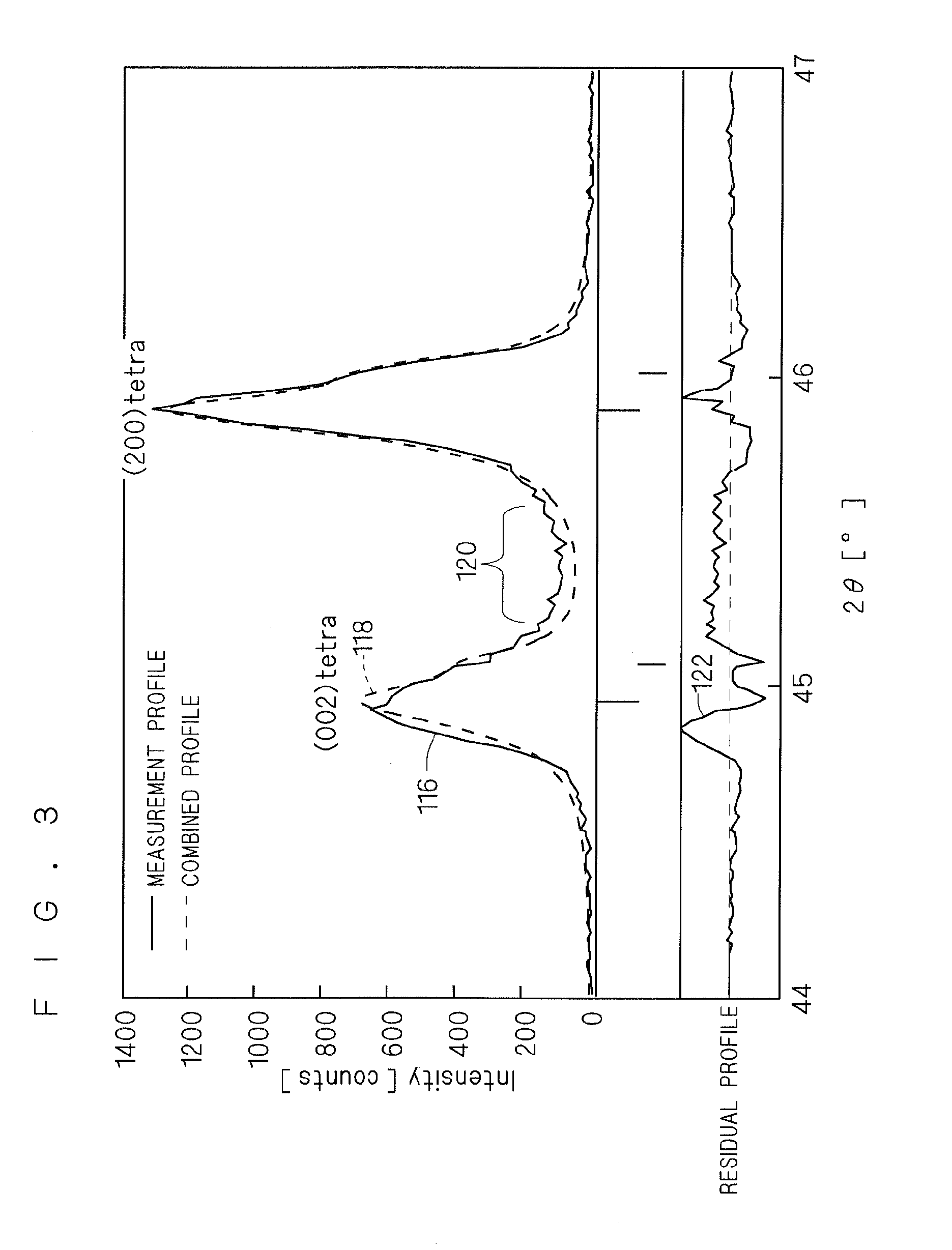
[0077]FIGS. 6 and 7 are diagrams illustrating the method of calculating the degree of c-axis orientation and the diffuse scattering intensity ratio according to the second embodiment. FIG. 6 is a flowchart showing a flow of calculation of the degree of c-axis orientation and the diffuse scattering intensity ratio according to the second embodiment. FIG. 7 is a chart showing an example of an X-ray diffraction profile according to the second embodiment. FIG. 7 shows an X-ray diffraction profile at angle 2θ=44° to 47° at which a peak appears on a (002) plane in the tetragonal system (denoted by “(002)tetra” in FIG. 7) and a peak appears on a (200) plane in the tetragonal system (denoted by “(200)tetra” in FIG. 7).

(a) Me...

third embodiment

3. Third Embodiment

[0097]A third embodiment relates to a method of manufacturing a piezoelectric / electrostrictive ceramics sintered body suited for manufacturing the piezoelectric / electrostrictive ceramics sintered body according to the first embodiment.

[0098]FIG. 8 is a flowchart showing a flow of manufacture of the piezoelectric / electrostrictive ceramics sintered body according to the third embodiment.

(a) Produce Piezoelectric / electrostrictive Ceramics Powder (Step S301)

[0099]For manufacturing the piezoelectric / electrostrictive ceramics sintered body, piezoelectric / electrostrictive ceramics powder having the composition described in “Composition” according to the first embodiment is first produced (step S301). At this time, piezoelectric / electrostrictive ceramics powder having slightly adjusted composition may be produced in view of volatilization, diffusion and the like during firing.

(b) Forming (Step S302)

[0100]Next, the piezoelectric / electrostrictive ceramics powder produced in...


PUM

PropertyMeasurementUnit
widthaaaaaaaaaa
aaaaaaaaaa
radiusaaaaaaaaaa

Abstract

An alkali niobate-based piezoelectric/electrostrictive ceramics sintered body including, as a main crystal phase, a perovskite type oxide containing at least one type of element selected from the group consisting of Li, Na and K as A site constituent elements and at least one type of element selected from the group consisting of Nb and Ta as B site constituent elements. The number of lattice-strained layers of the piezoelectric/electrostrictive ceramics sintered body is preferably small. A diffuse scattering intensity ratio, which is a ratio of an intensity of diffuse scattering by a lattice-strained layer present near a domain wall to a sum of an X-ray diffraction intensity of a first lattice plane and that of a second lattice plane different in interplanar spacing from the first lattice plane due to crystallographic symmetry reduction is preferably 0.5 or lower.

Description

BACKGROUND OF THE INVENTION[0001]1. Field of the Invention[0002]The present invention relates to an alkali niobate-based piezoelectric / electrostrictive ceramics sintered body having a large electric-field-induced strain during application of a high electric field and a method of calculating a diffuse scattering intensity ratio, which method can easily obtain a diffuse scattering intensity ratio that serves as an index for improving a electric-field-induced strain of an alkali niobate-based piezoelectric / electrostrictive ceramics sintered body during application of a high electric field.[0003]2. Description of the Background Art[0004]A piezoelectric / electrostrictive actuator has an advantage in that a displacement can be accurately controlled in the order of submicrons. In addition to the accurate control of a displacement, a piezoelectric / electrostrictive actuator using a piezoelectric / electrostrictive ceramics sintered body as a piezoelectric / electrostrictive body, in particular, h...

Claims


Application Information

Patent Timeline
Patent Type & Authority Applications(United States)
IPC IPC(8): H01L41/187G01N23/20C04B35/00H01L41/083H01L41/18H01L41/22H01L41/333H01L41/39
CPCC04B35/495H01L41/187C04B2235/3203C04B2235/3241C04B2235/3267C04B2235/3272C04B2235/3275C04B2235/3279C04B2235/3281C04B2235/3284C04B2235/3289C04B2235/3294C04B2235/3298C04B2235/528C04B2235/5445C04B2235/656C04B2235/661C04B2235/662C04B2235/761C04B2235/762C04B2235/768C04B2235/783C04B2235/3201H10N30/2047H10N30/8542H10N30/50H10N30/053H10N30/074
Inventor KAIGAWA, KAZUYUKITANAKA, RITSUYAMAGUCHI, HIROFUMI
Owner NGK INSULATORS LTD
Why Eureka
Try Eureka