
Header with integral antenna for implantable medical devices

Inactive Publication Date: 2010-01-28
ANGEL MEDICAL SYST
View PDF8 Cites 76 Cited by
  • Summary
  • Abstract
  • Description
  • Claims
  • Application Information

AI Technical Summary

Benefits of technology

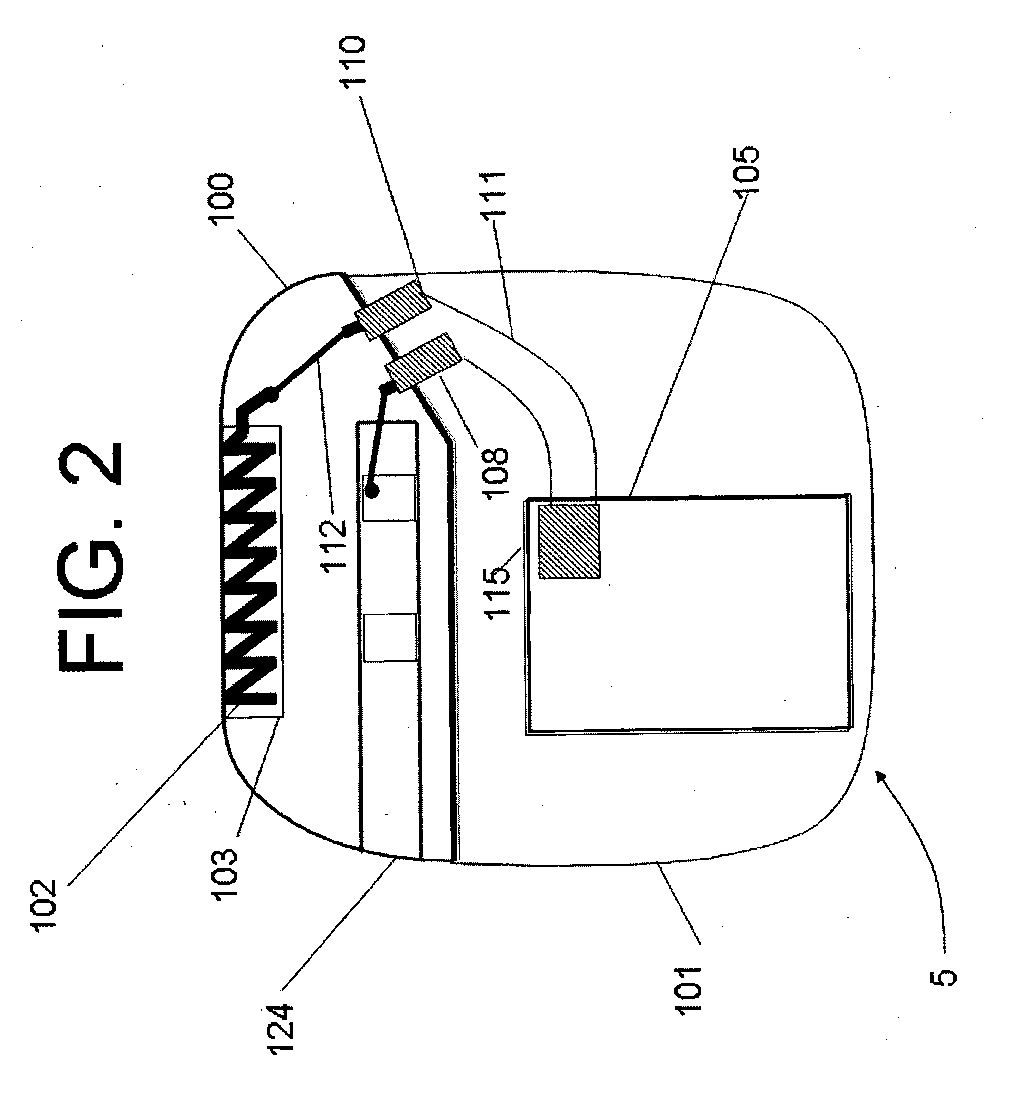
[0008]A preferred manufacturing process is also described according to which a header is pre-molded with a compartment (e.g. the above mentioned bore) for receiving an antenna. An antenna is then disposed within the compartment and the resulting assembly is then attached to the device housing so that a wire runs through a feed-through in the housing and through a channel in the header. The wire is electrically connected to the antenna. The antenna compartment is then backfilled with silicone and then sealed with a cover. By utilizing this process, an antenna can be assembled after the header is molded, offering the flexibility to change the antenna to any length and any material, and eliminates an expensive insert-molding process. Also, this process allows the antenna to have a wide variety of shapes.

Problems solved by technology

However, because the human body is a lossy multi-layered dielectric media, optimum antenna length in a human body is much smaller than antenna length in free space.
The presence of the human body complicates antenna design, especially in light of the relatively high frequency band associated with MICS and the difficulties associated with integrating an antenna with a biocompatible implantable device.

Method used


Image

  • Header with integral antenna for implantable medical devices
  • Header with integral antenna for implantable medical devices
  • Header with integral antenna for implantable medical devices

Examples


Embodiment Construction

[0029]Various references will be made to cuboid components (e.g. a substrate) defined by a length, depth and height, having two major parallel surfaces (length×depth surfaces) that generally have a much greater surface area than the other four surfaces. For convenience, when referring to the orientation of the cuboid with respect to another surface, the cuboid will be treated as a surface, not a volume, defined by either of the two major parallel surfaces. Thus, for example, if a substrate is said to be mounted parallel to a container's surface, then either of the cuboid's two major surfaces are mounted parallel to the container's surface.

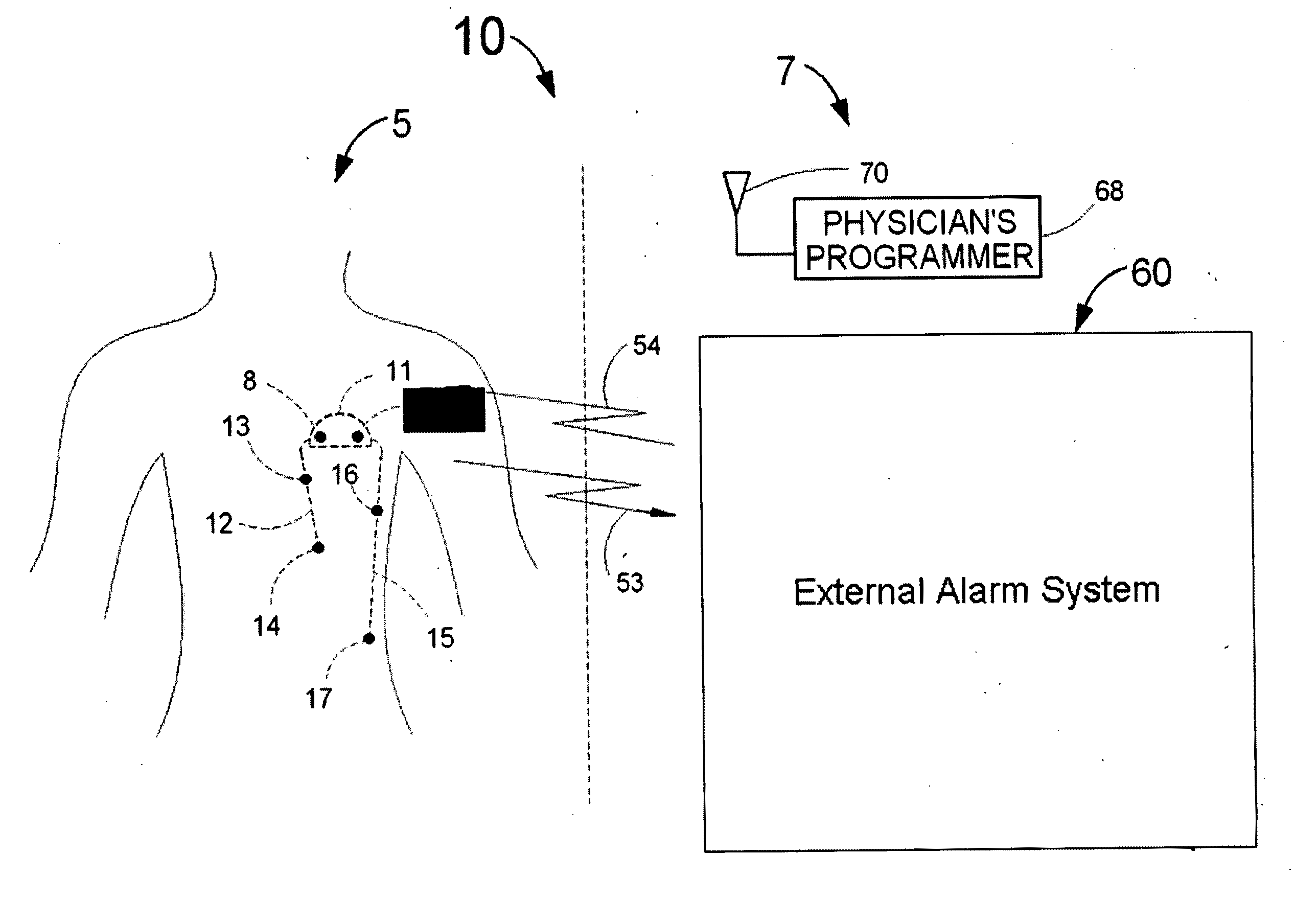
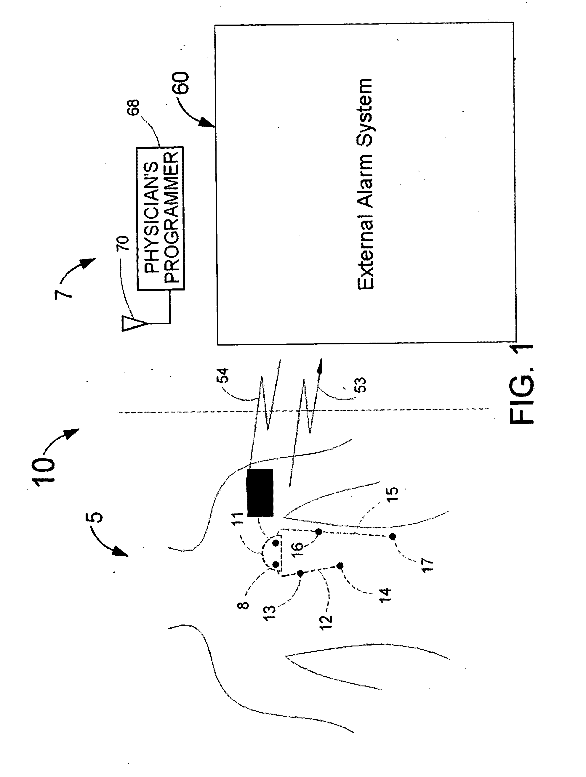
[0030]FIG. 1 illustrates one embodiment of a system 10 consisting of a patient side system 5 and external equipment 7. The patient side system includes an implanted medical device 11 that comprises a housing 101 (FIG. 2) that contains a transceiver (not shown) and electronic circuitry that can detect a cardiac event such as an acute myocardial infa...


PUM


Abstract

Antenna assemblies for an implantable medical device are disclosed. The implantable medical device comprises a hermetically sealed housing, typically formed of titanium materials, and electronics, including a transceiver, disposed therein. An antenna is disposed in an air, gas or plastic dielectric filled compartment within a header, which is attached to the housing. The header is premolded so as to create the compartment. The antenna is then placed within the compartment, which is then sealed.

Description

FIELD OF USE[0001]This invention is in the field of implantable devices. More particularly, the invention relates to antenna designs for implantable medical devices.BACKGROUND OF THE INVENTION[0002]The medical implant communications service (MICS) Radio-Frequency (RF) band for implantable devices is a wireless telecommunications standard that describes communication in a frequency band between 402 MHz and 405 MHz. An implanted device operating according to this standard should be able to send / receive data to / from external devices that are at least 2 meters away from the implant. The maximum allowed power on the body surface from RF emanating from the implanted device is 25 micro-Watts.[0003]The free-space wavelength of RF at 403 MHz is 74.4 cm. However, because the human body is a lossy multi-layered dielectric media, optimum antenna length in a human body is much smaller than antenna length in free space. The presence of the human body complicates antenna design, especially in ligh...

Claims


Application Information

Patent Timeline
IPC IPC(8): H01Q1/40
CPCA61B5/0031A61B5/0402A61N1/37229A61N1/375A61N1/3758H01Q9/42H01Q1/36H01Q1/362H01Q1/40H01Q9/0421H01Q9/26A61N1/378A61N1/37518A61B5/318
Inventor BASHYAM, JACOBLONG, JAMESJOHNSON, STEVEN R.
Owner ANGEL MEDICAL SYST
Learn More