Read enhancement for memory

Active Publication Date: 2010-01-28
NXP BV
View PDF11 Cites 19 Cited by
  • Summary
  • Abstract
  • Description
  • Claims
  • Application Information

AI Technical Summary

Benefits of technology

[0012]It is an object of the invention to provide a read-out mechanism fo

Problems solved by technology

One drawback of the described prior art solution consists in the high power consumption phase while the currents or voltages are applied during the read out of the information contained in the memory element.
High power consumption is disadvantageous particularly for mobile devices, i.e. low power applications.
However, such a measure impairs analogue sensing sensitivity and robustness and impacts the yield and th

Method used


Image

  • Read enhancement for memory
  • Read enhancement for memory
  • Read enhancement for memory

Examples


Embodiment Construction

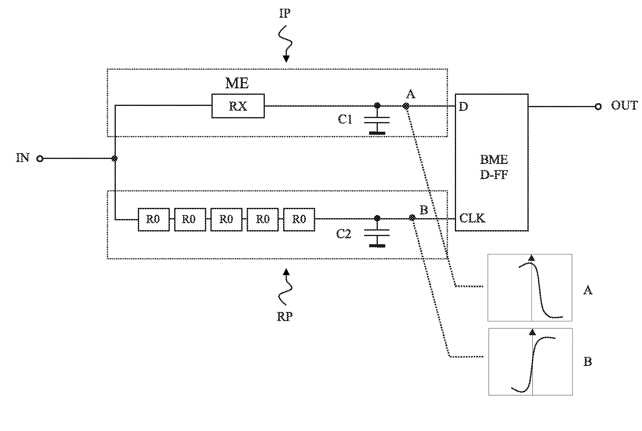
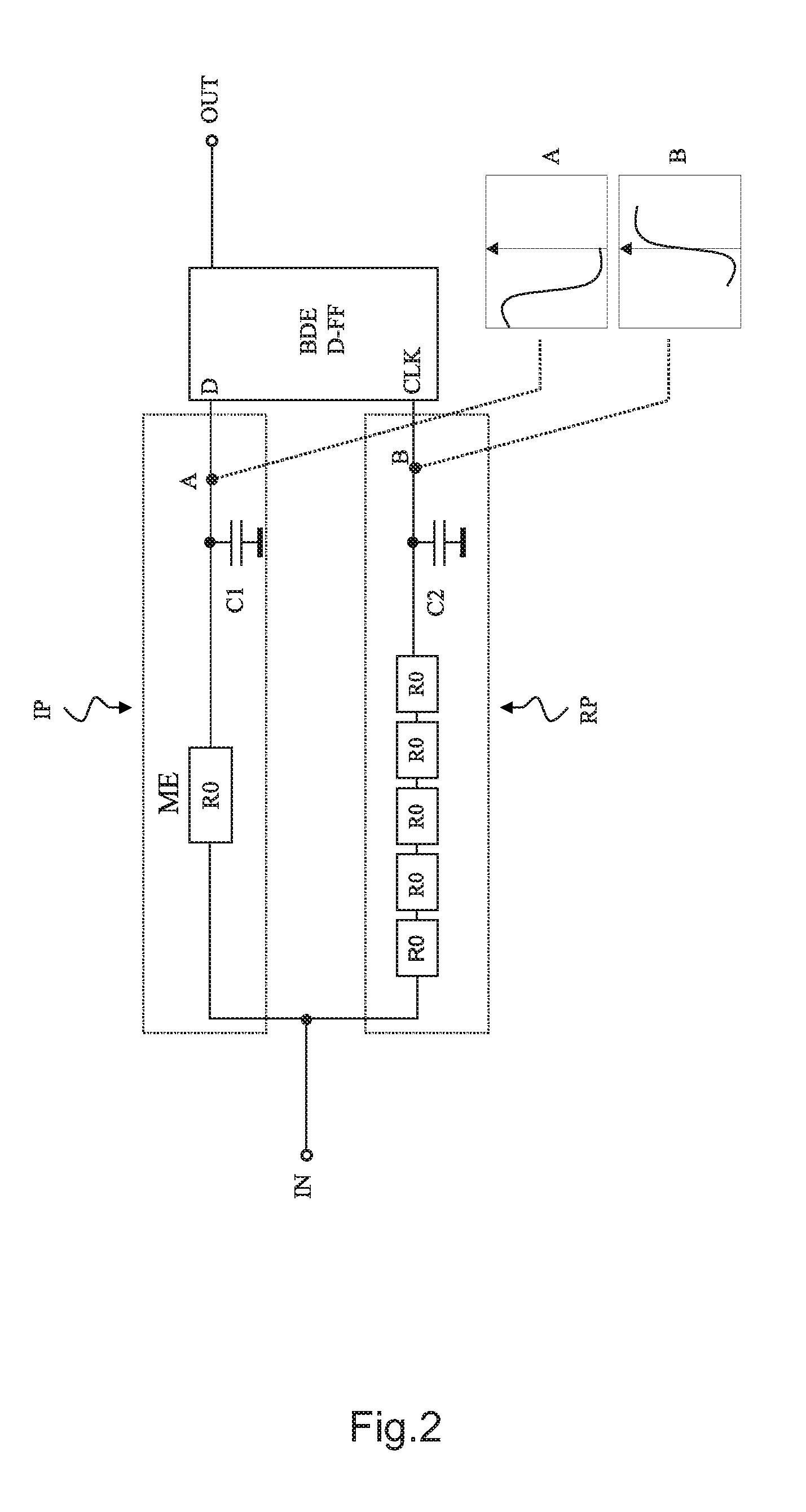
[0039]FIG. 1 shows a simplified basic arrangement according to an embodiment of the present invention. The information path IP includes the memory element ME. The reference path RP includes a reference element REF. However, the reference path RP does not need to provide a reference element REF as long as the electrical properties of the reference path RP are known, and as long as those properties are suitable for the invention. According to the embodiment shown in FIG. 1, a reference element REF is coupled to the reference path. This reference element is designed in relation to the electrical properties of the memory element ME. If for example, the memory element ME is a polysilicon fuse, having a first resistance in a unwritten state and a second resistance in written state, the reference element can be designed to provide a resistance that is approximately in the middle of these values. The memory element can also be one of the above mentioned elements, as MRAM, FRAM, PMC, or an E...


PUM


Abstract

An electronic circuitry is provided for reading out a memory element (ME). The electronic circuitry comprises a first electronic path (IP) being coupled to the memory element (ME), a second electronic path (RP) having predetermined electrical properties, and a basic detection element (BDE) being coupled to the first and second electronic paths (IP, RP) such that the information contained in the memory element (ME) can be determined by the basic detection element (BDE) based on the relation of a digital signal being propagated over the first path (IP) to a digital signal being propagated over the second path (RP).

Description

FIELD OF THE INVENTION[0001]The invention relates to memory devices, more specifically to an electronic circuitry for reading information contained in a memory element a corresponding method for reading out information and a method for designing a circuitry for reading information contained in a memory element.BACKGROUND OF THE INVENTION[0002]It is known in the art to store information or data in various kinds of memories. Generally, memory devices are known, which store information by electrical charges on capacitances, or by changes in resistance in an either volatile or non-volatile manner.[0003]One example for a memory element is a polysilicon fuse. In order to write information on the fuse, typically a small conductive path of polysilicon is provided to be destroyed by an over current imposed to the path. Other techniques apply external laser light to dissect conductive portions of the fuse. A modified fuse, exhibits modified electrical properties, e.g. a larger electrical resi...

Claims


Application Information

Patent Timeline
IPC IPC(8): G11C7/00G06F17/50
CPCG11C7/065G11C2013/0054G11C13/004G11C13/0061
Inventor MAYOR, CEDRIC
Owner NXP BV
Why Eureka
Try Eureka