Protective tubes for thermocouples

Inactive Publication Date: 2010-01-28
ALSTOM TECH LTD
View PDF9 Cites 12 Cited by
  • Summary
  • Abstract
  • Description
  • Claims
  • Application Information

AI Technical Summary

Benefits of technology

[0012]One of numerous aspects of the present invention relates to a material suitable for producing protective tubes for thermocouples that can be used without any problems in an oxidizing atmosphere in gas turbines at extremely high temperat

Problems solved by technology

This production method, but also the material compositions described, disadvantageously mean, inter alia, that these alloys are very expensive and have anisotropic properties.
Although this polycrystalline material has good oxidation resistance at temperatures

Method used


Image

  • Protective tubes for thermocouples
  • Protective tubes for thermocouples
  • Protective tubes for thermocouples

Examples


Example

[0019]The invention is explained in more detail below on the basis of exemplary embodiments and the drawing.

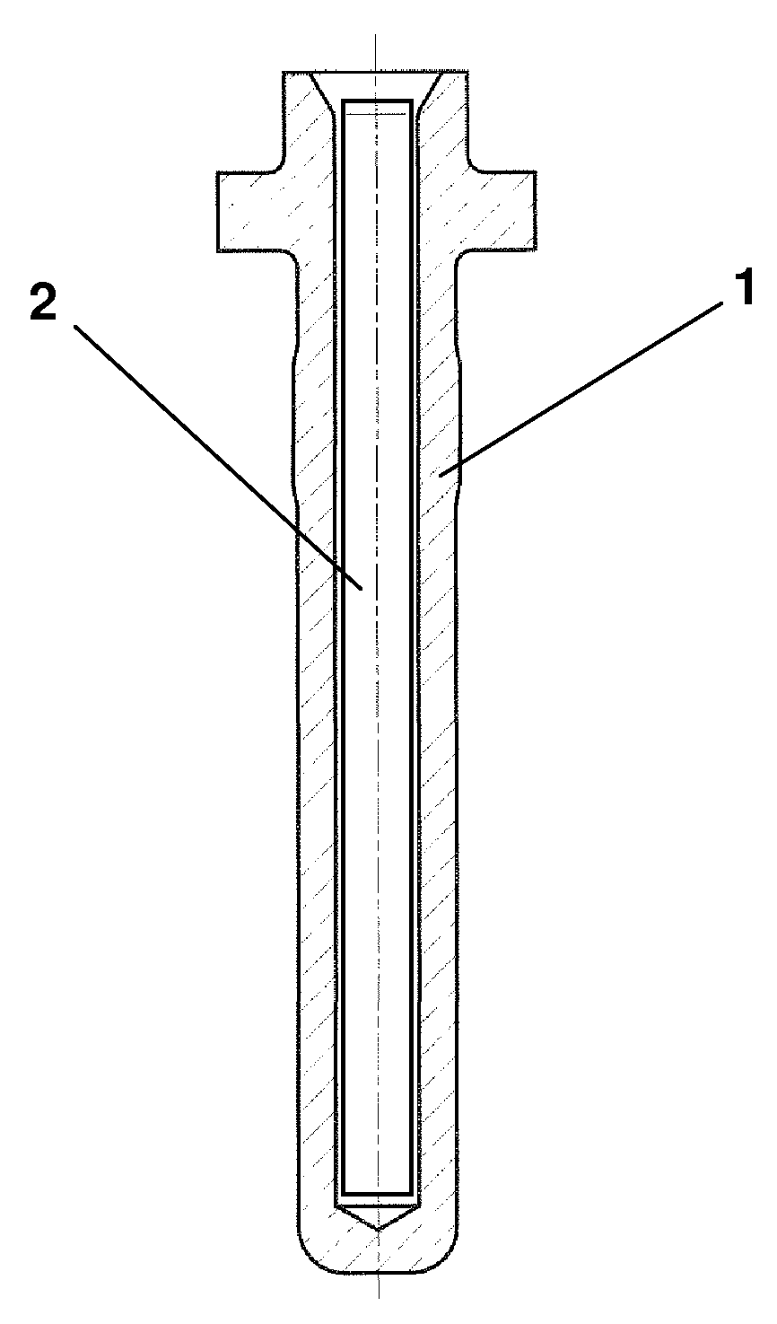
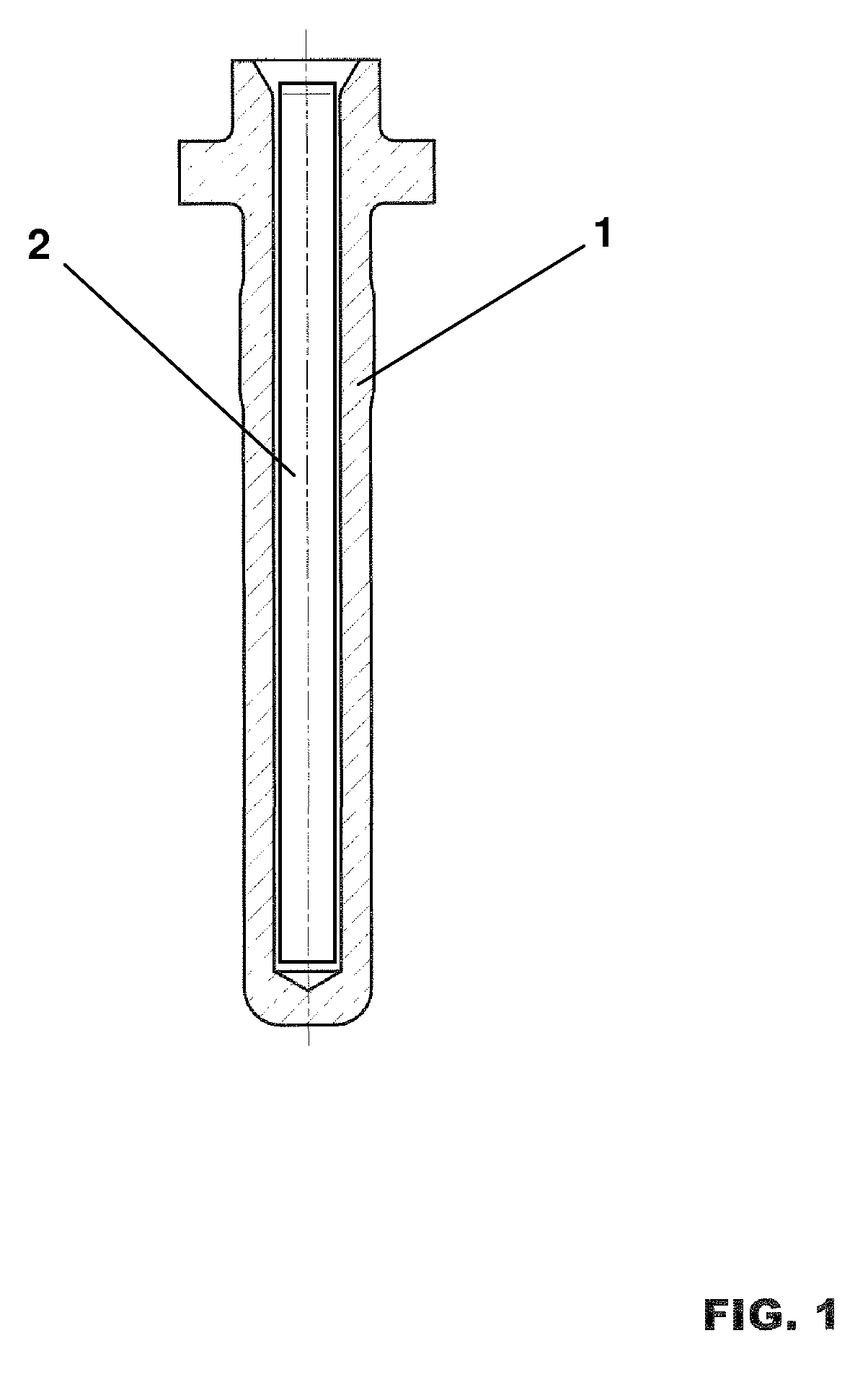
[0020]FIG. 1 schematically shows a section through a protective tube for thermocouples (sleeves for thermocouples), as is used by ALSTOM for measuring the temperature of the gas flow in gas turbines with sequential combustion. To date, protective tubes of this type have been produced by a powder metallurgy process from the ODS FeCrAl comparative alloy PM 2000 known from the prior art.

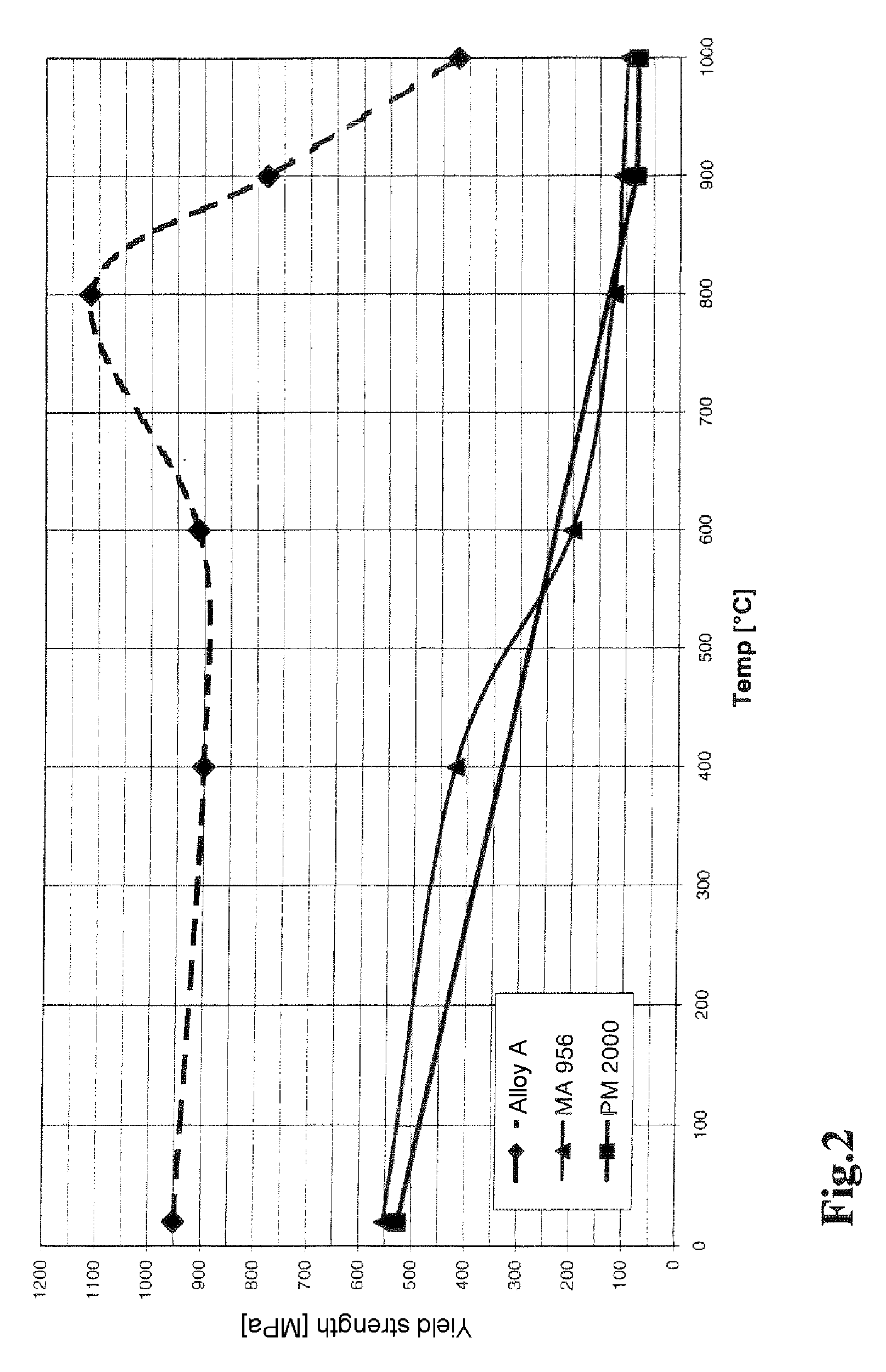
[0021]According to the invention, the protective tubes were produced from various single-crystal nickel-based superalloys and investigated with regard to the oxidation behavior and the mechanical properties at temperatures up to 1100° C.

[0022]Table 1 lists the respective chemical composition of the investigated alloys; the alloying constituents are specified in % by weight and, at points marked specifically, in ppm:

TABLE 1Compositions of the investigated alloys for protective tubesConstituentAlloy...


PUM

PropertyMeasurementUnit
Temperatureaaaaaaaaaa
Poweraaaaaaaaaa
Poweraaaaaaaaaa

Abstract

Protective tubes for thermocouples exposed to oxidizing atmospheres at temperatures in the region of approximately 1100° C. are produced from a single-crystal nickel-based superalloy, preferably from an alloy having the following chemical composition (in % by weight): 7.7-8.3 Cr, 5.0-5.25 Co, 2.0-2.1 Mo, 7.8-8.3 W, 5.8-6.1 Ta, 4.9-5.1 Al, 1.3-1.4 Ti, 0.11-0.15 Si, 0.11-0.15 Hf, 200-750 ppm C, 50-400 ppm B, remainder nickel and unavoidable impurities. Protective tubes of this type exhibit good strength and good oxidation resistance under severe stress conditions.

Description

[0001]This application claims priority under 35 U.S.C. §119 to Swiss application no. 01173 / 08, filed 25 Jul. 2008, the entirety of which is incorporated by reference herein.BACKGROUND[0002]1. Field of Endeavor[0003]The invention relates to protective tubes for thermocouples exposed to oxidizing atmospheres at very high temperatures in the region of approximately 1100° C. Severe stress conditions of this type occur, for example, when measuring the temperature in gas turbines.[0004]2. Brief Description of the Related Art[0005]The type GT24 / GT26 gas turbines of ALSTOM, which are known from the prior art, operate on the basis of the sequential combustion principle. This involves the hot gases provided in a first combustion chamber acting on a first turbine, with the exhaust gases which flow out of this first turbine then being prepared in a second combustion chamber to re-form hot gases which then act on a second turbine. The second combustion chamber is designed for spontaneous ignitio...

Claims


Application Information

Patent Timeline
IPC IPC(8): G01K7/02B32B1/08B32B15/01
CPCC22C19/057C30B29/52Y10T428/12G01K7/02G01K13/02G01K1/105
Inventor NAZMY, MOHAMEDKUNZLER, ANDREASBANDIERA, GIUSEPPEZINN, HANSPETER
Owner ALSTOM TECH LTD
Why Eureka
Try Eureka