Optical signal processing device

a technology of optical signal and processing device, which is applied in the direction of optical elements, electromagnetic repeaters, instruments, etc., can solve the problems of limited practical transmission distance, serious deformation of optical s/n ratio, and waveform distortion

Inactive Publication Date: 2010-01-28
FUJITSU LTD
View PDF15 Cites 32 Cited by
  • Summary
  • Abstract
  • Description
  • Claims
  • Application Information

AI Technical Summary

Benefits of technology

[0019]An optical signal processing device according to one aspect of the invention includes nonlinear optical medium to which signal light, and first and second pumping lights having wavelengths different from the signal light are input; first and second power controllers, provided at the input side of the nonlinear optical medium, to control the powers of the first and the second pumping lights so that a predetermined gain is obtained in the nonlinear optical medium; and a polarization controller, provided at the input side of the nonlinear optical medium, to adjust the first and the second pumping lights so that polarization states of the first and the second pumping lights are mutually orthogonal.

Problems solved by technology

However, waveform distortion remains and the optical S / N ratio is seriously degraded by an ASE noise that is caused by an optical amplifier even if dispersion compensation of high precision and an optical amplifier of high quality are combined.
Therefore, a practical transmission distance is limited.
With the conventional technology, however, the configuration of an optical circuit that does not depend on the polarization state of signal light is complicated, and its loss is large.
Therefore, the efficiency of optical signal processing is low.
Especially, in an optical signal processing device that collectively processes the waveforms of a plurality of optical signals transmitted with wavelength-division multiplexing (WDM), such a loss exerts considerable influences.

Method used


Image

  • Optical signal processing device
  • Optical signal processing device
  • Optical signal processing device

Examples


first embodiment

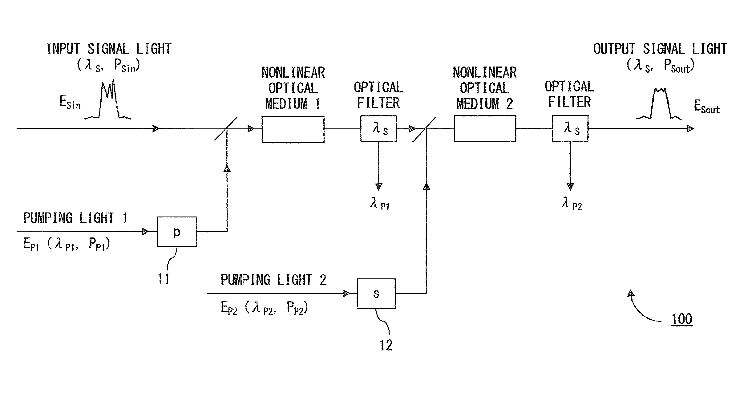
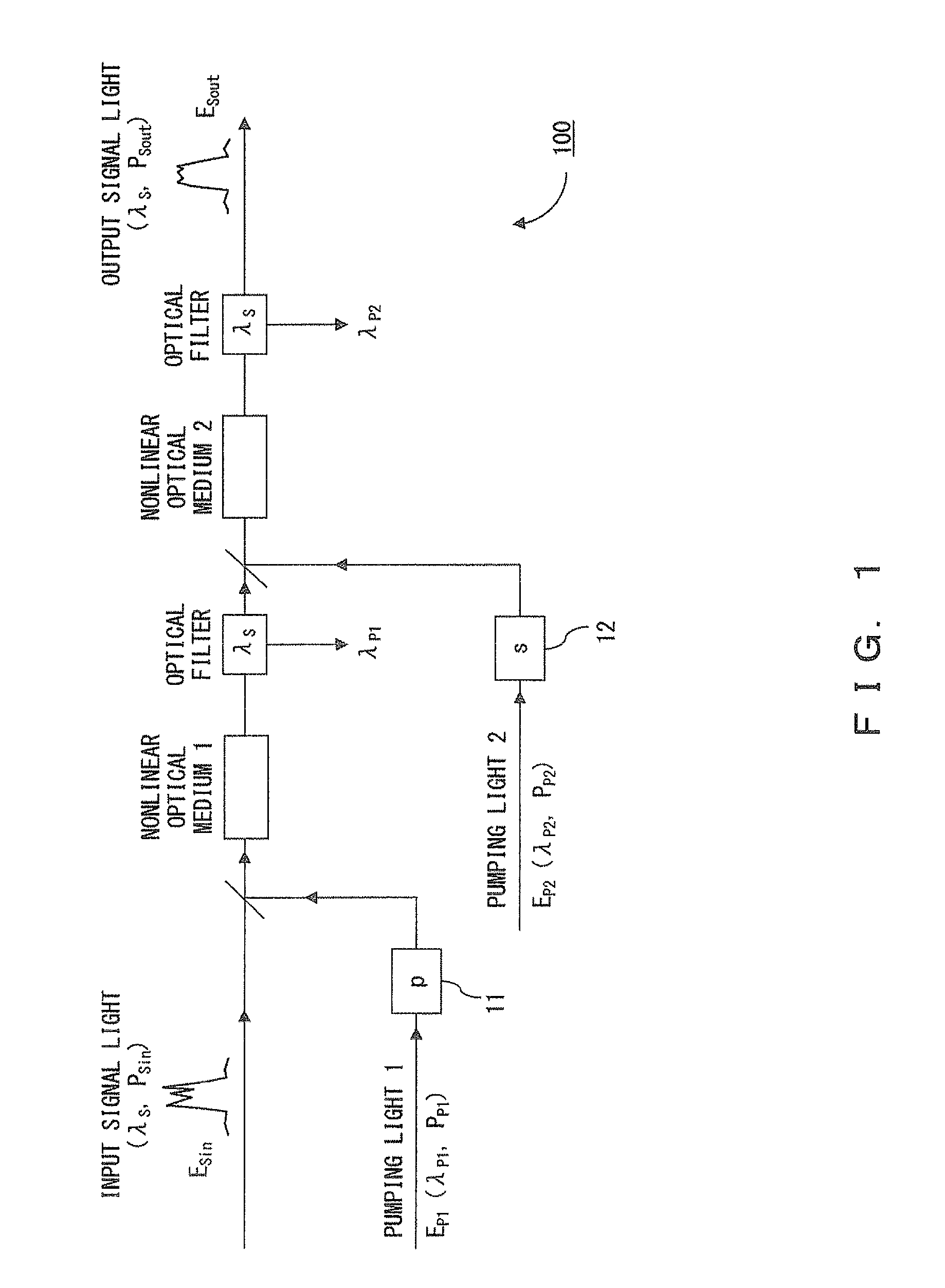
[0056]FIG. 3 illustrates a configuration of an optical signal processing device according to a first embodiment. The basic configuration of the optical signal processing device according to the first embodiment is the same as the optical signal processing device illustrated in FIG. 1. However, optical fibers 21 and 22 are respectively used as the nonlinear optical media 1 and 2 in the first embodiment.

[0057]The input powers of the signal light (ES), the pumping light (EP1) and the pumping light (EP2) are respectively controlled by power controllers. The power controllers are respectively implemented, for example, with an optical amplifier or an optical attenuator. Alternatively, the power controllers may be implemented by combining an optical amplifier and an optical attenuator. At this time, the powers of the pumping lights 1 and 2 are controlled, for example, to generate mutually identical or almost identical optical parametric gains in the optical fibers 21 and 22. Moreover, the ...

second embodiment

[0078]To generate sufficient gain saturation for every polarization state of signal light, pumping light in a polarization state of another direction may be used in addition to the above described one pair of mutually orthogonal pumping lights. Here, a configuration further using another pair of pumping lights EP3 and EP4, the polarization direction of which is 45 degrees from the pumping lights EP1 and EP2, is described.

[0079]FIG. 7 illustrates a configuration of an optical signal processing device according to the second embodiment. The optical signal processing device according to the second embodiment includes cascade-connected optical fibers 21 to 24. All of the optical fibers 21 to 24 are nonlinear optical fibers, and have the same characteristic in this embodiment.

[0080]To the optical fibers 21, 22, 23 and 24, pumping light 1 (EP1), pumping light 2 (EP2), pumping light 3 (EP3) and pumping light 4 (EP4), which are generated by pumping light sources not illustrated in FIG. 7, a...

third embodiment

[0085]In the first and the second embodiments, the power of the signal light must be increased to a certain extent in order to implement the optical limiter function. Specifically, the input power PSin of the signal light must be higher than the threshold power P1 in FIGS. 4A and 4B. However, it is not always possible to make the input power of the signal light higher than the threshold power P1. Especially, the power of each optical signal is low in a WDM system where a plurality of optical signals are carried.

[0086]FIG. 9 illustrates a configuration of an optical signal processing device according to the third embodiment. In this optical signal processing device, control light ECont is provided to the optical fibers 21 and 22. The wavelength λCont of the control light is different from the wavelength λS of the signal light, and the wavelengths λP1 and λP2 of the pumping lights. In FIG. 9, the control light is provided only to the optical fiber 21. Actually, however, another contro...


PUM

PropertyMeasurementUnit
wavelengthsaaaaaaaaaa
output poweraaaaaaaaaa
poweraaaaaaaaaa

Abstract

An optical signal processing device has nonlinear optical medium, first and second power controllers, and polarization controllers. To the nonlinear optical medium, signal light, and first and second pumping lights having wavelengths different from the signal light are input. The first and the second power controllers are provided at the input side of the nonlinear optical medium, and control the powers of the first and the second pumping lights so that a predetermined gain is obtained in the nonlinear optical medium. The polarization controllers are provided at the input side of the nonlinear optical medium, and adjust the first and the second pumping lights so that the polarization states of the first and the second pumping lights are mutually orthogonal.

Description

CROSS-REFERENCE TO RELATED APPLICATIONS[0001]This application is based upon and claims the benefit of priority of the prior Japanese Patent Application No. 2008-188657, filed on Jul. 22, 2008, the entire contents of which are incorporated herein by reference.FIELD[0002]The present invention relates to an optical signal processing device. The present invention may be applied, for example, to an optical switch, a wavelength converter, a device for shaping the waveform of an optical signal degraded by optical fiber transmission, a device for improving the quality (especially, an optical S / N) of an optical signal degraded by noise caused by an optical fiber transmission, and the like.BACKGROUND[0003]In an optical communication system, the limits of a transmission speed (bit rate of data) or a total data transmission capacity (transmission speed per channel×number of channels), and a possible transmission distance depend on an optical S / N ratio (Optical Signal-to-Noise Ratio), and the wa...

Claims


Application Information

Patent Timeline
Patent Type & Authority Applications(United States)
IPC IPC(8): G02B6/00G02F1/39H04B10/07H04B10/2507H04B10/29H04B10/294
CPCG02F1/3536G02F1/395H04B10/299G02F2203/06G02F2201/16G02F2203/26
Inventor WATANABE, SHIGEKI
Owner FUJITSU LTD
Why Eureka
Try Eureka