Composite material and method for increasing z-axis thermal conductivity of composite sheet material

a composite material and thermal conductivity technology, applied in the field of structural composite materials, can solve the problems of reducing affecting the etc., and achieve the effect of increasing the z-axis thermal conductivity of the composite material

Inactive Publication Date: 2010-01-28
FLORIDA STATE UNIV RES FOUND INC
View PDF10 Cites 75 Cited by
  • Summary
  • Abstract
  • Description
  • Claims
  • Application Information

AI Technical Summary

Benefits of technology

[0006]Methods for making a composite material and a method of making the same have been developed. The method increases the Z-axis thermal conductivity of the composite material. In certain embodiments, the method for making a composite material comprises providing at least one sheet which comprise woven or non-woven fibers and stitching a plurality of stitches of a thermally conductive fiber through the at least one sheet, thereby forming a stitched composite material. The woven or non-woven fibers comprise glass fibers, carbon fibers, aramid fibers, or nanoscale fibers.

Problems solved by technology

The use of Z-pins involves a costly post-process using small (e.g., sub-millimeter) diameter cured composite rods.
The process of forming the holes in the composite, however, may damage fibers and / or a resin matrix of the composite.
Therefore, while these Z-pin products may increase a composite's through-thickness thermal conductivity, it may unintentionally and undesirably diminish certain strength or other desirable properties of the composite material.

Method used


Image

  • Composite material and method for increasing z-axis thermal conductivity of composite sheet material
  • Composite material and method for increasing z-axis thermal conductivity of composite sheet material
  • Composite material and method for increasing z-axis thermal conductivity of composite sheet material

Examples


example 1

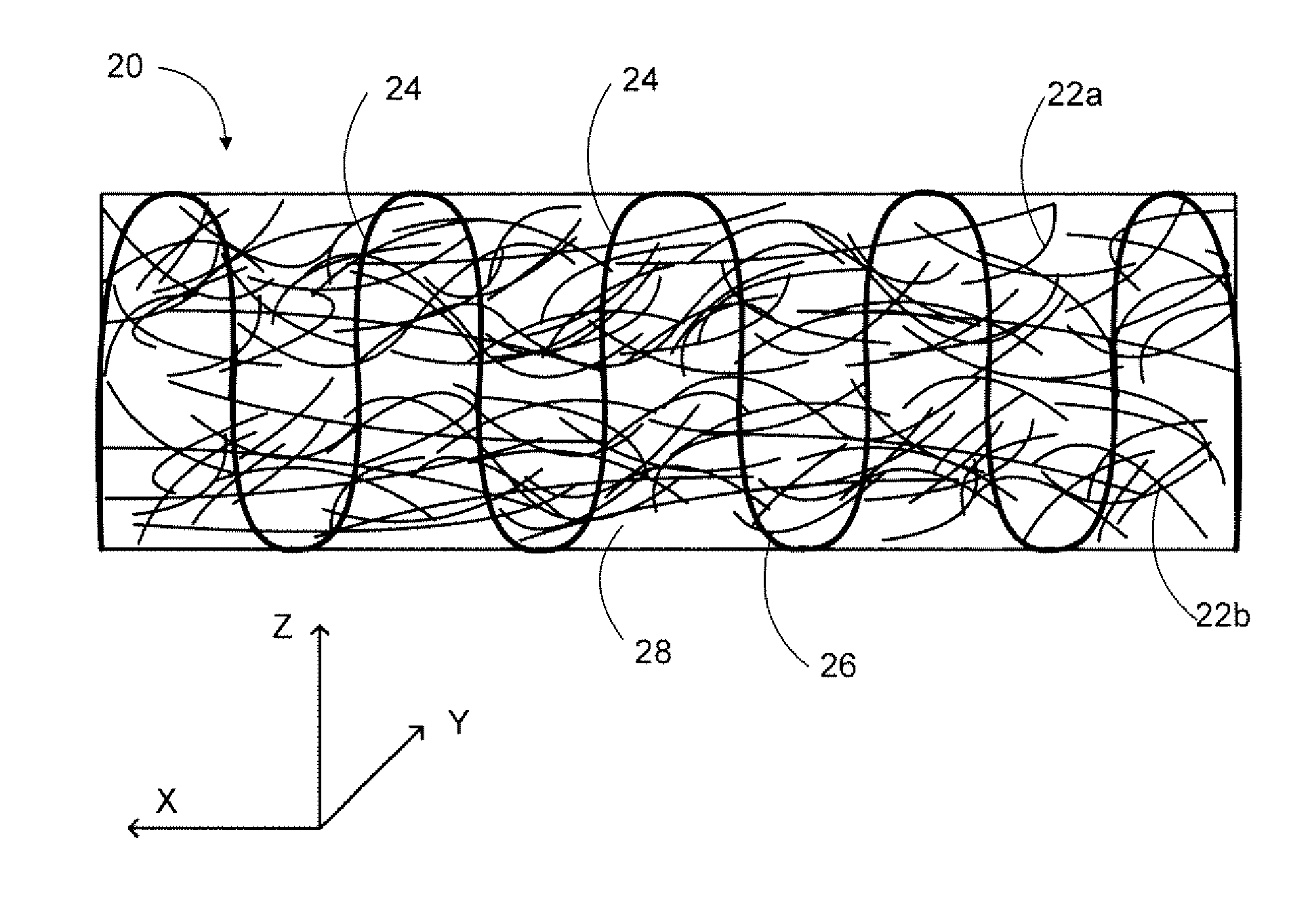
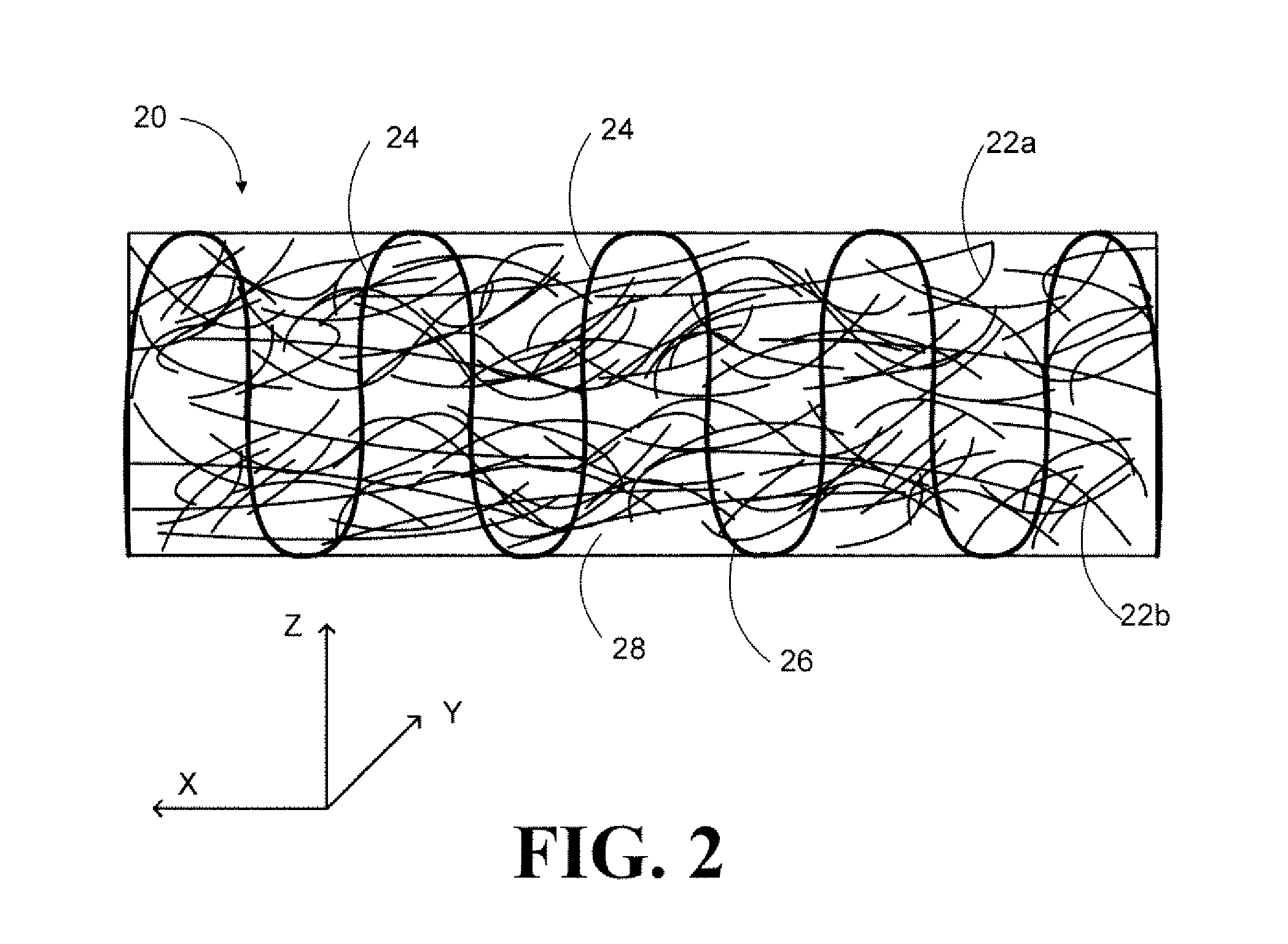
[0068]A fiberglass fabric composite with through-thickness stitched copper wires (i.e., 0.006″ high purity copper wire from McMaster-Carr) and CNT yarn (i.e., 3Tex nanotube yarns from Nanocomp (about 20-80 microns in diameter. 2-5 gram / kilometer, and 1.33 g / cm2 density)) was made. A fine point needle was used to stitch the wires and yarns through the fiberglass material to form the composite. The composite was then cured with Epon 862 from flexion Specialty Chemicals using a VIP process. The stitching patterns, copper wires, and nanotube yarns were visible at the surface of the samples. The volume fractions of copper and nanotube yarns in the composites were 5 volume % and 0.4 volume % respectively.

example 2

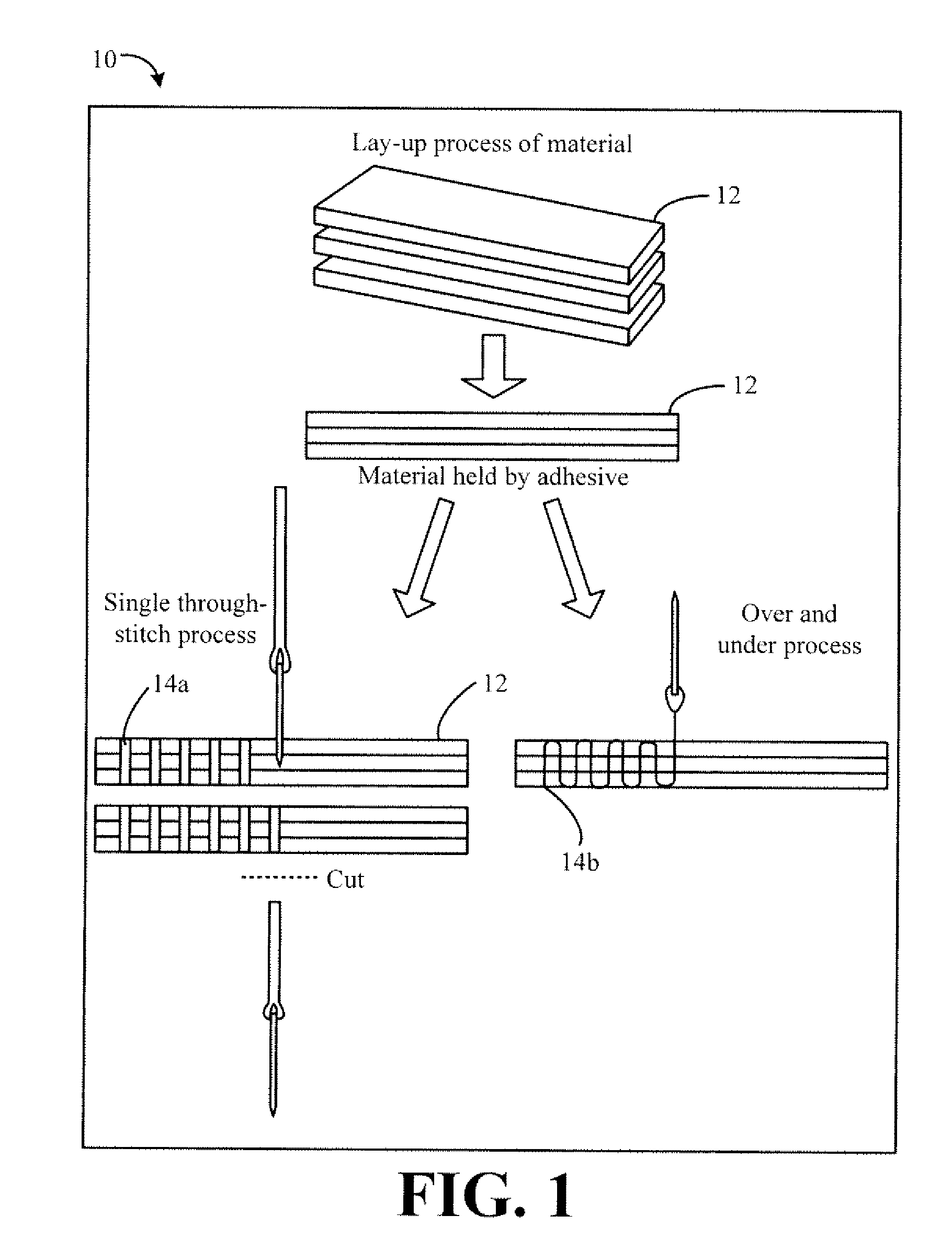
[0069]Three samples were made with three layers of E-glass fiber and Epon 862. Sample 1 had 0.4% CNT yarn (i.e., 3Tex nanotube yarns from Nanocomp (about 20-80 microns in diameter, 2-5 gram / kilometer, and 1.33 g / cm2 density)) by volume fraction (Vf), Sample 2 had 1.8% copper by Vf, and Sample 3 had 5.0% copper by Vf stitched into a E-glass fiber preform. The copper wire was 0.006″ high purity copper wire from McMaster-Carr. The CNT yarn was stitched using the over-and-under technique, while the copper sample was made with the single through-stitch technique.

[0070]The experimental results showed significant increases in through-thickness thermal conductivity. The fiberglass samples were tested in a Netzsch LEA 457 Microflash machine and the thermal diffusivity results are shown in FIGS. 3-6. Table 1 shows the comprehensive results data collected on the samples stitched with CNT yarn and copper wire and provide the calculated thermal conductivity. The thermal conductivity was calculat...


PUM

PropertyMeasurementUnit
volume fractionaaaaaaaaaa
thicknessaaaaaaaaaa
diameteraaaaaaaaaa

Abstract

Methods are provided for making a composite material that includes (a) providing at least one sheet which includes woven or non-woven glass fibers, carbon fibers, aramid fibers, or nanoscale fibers; and (b) stitching a plurality of stitches of a thermally conductive fiber through the at least one sheet in a Z-axis direction to form paths of higher conductivity through the sheet of material to increase its thermal conductivity in the Z-axis.

Description

CROSS-REFERENCE TO RELATED APPLICATION[0001]This application claims benefit of U.S. Provisional Application No. 61 / 083,786, filed Jul. 25, 2008, which is incorporated herein by reference.BACKGROUND OF THE INVENTION[0002]This invention relates generally to structural composite materials, and more particularly to composite and methods for imparting higher through-thickness thermal conductivity to laminate and other composite material structures.[0003]In conventional fiber-reinforced composites, few, if any, through-thickness conducting paths exist due to the microstructure nature of the composites (e.g., in-plane or 2D laminate structures and chopped fiber / resin mixture structures). Therefore, the composites' through-thickness thermal conductivities are usually only slightly higher than those of neat resin matrices. For example, the through-thickness thermal conductivity of carbon fiber-reinforced, resin matrix composite laminates is usually about 0.2-0.4 W / mK; and the through-thickne...

Claims


Application Information

Patent Timeline
Patent Type & Authority Applications(United States)
IPC IPC(8): B32B3/02B05D7/02D04H11/00D03D25/00D03D11/00D05B1/00
CPCD03D15/0011D03D15/0061D04H1/42D04H1/52Y10T428/24041D10B2101/12D10B2331/021D10B2505/02D04H13/008D04H1/4218D04H1/4242D04H1/4342D04H1/4374Y10T442/696Y10T442/659Y10T442/655Y10T442/3976Y10T442/339Y10T442/3472D03D15/33D03D15/267D04H1/43838
Inventor LIANG, ZHIYONGWANG, BENZHANG, CHUNZIMMER, MICHAEL M.
Owner FLORIDA STATE UNIV RES FOUND INC
Why Eureka
Try Eureka