Osmotic Heat Engine

a heat engine and osmotic technology, applied in the direction of machines/engines, reverse osmosis, mechanical equipment, etc., can solve the problems of deltas, also known as “open loop” pro, and many operational and design limitations, so as to hinder the osmotic flow

Inactive Publication Date: 2010-02-04
YALE UNIV
View PDF22 Cites 48 Cited by
  • Summary
  • Abstract
  • Description
  • Claims
  • Application Information

AI Technical Summary

Benefits of technology

[0019]It is an object of the present invention to provide an osmotic heat engine that includes dilute (nearly deionized) water as a working flui

Problems solved by technology

However, an important restriction regarding the adoption of new fuels and energy technologies is the cost of power produced by these means.
While subsidies and other forms of artificial support may assist in the introduction of these renewable energy sources, successful displacement of traditional fuels must necessarily be driven by total energy costs.
PRO processes at river deltas, also known as “open loop” PRO, have several operational and design limitations.
Another difficulty arises from the low differential osmotic pressures found between many natural feed waters.
Unfortunately, the volumetric flow of water into these water bodies is somewhat small and hence will yield limited power for even a well designed PRO process.
Sea water, for example, has an osmotic pressure of approximately 2.53 MPa (25 atm), which does not allow for the high hydraulic pressures that are desirable for efficient power production.
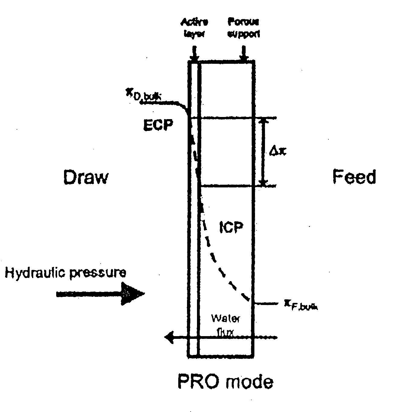
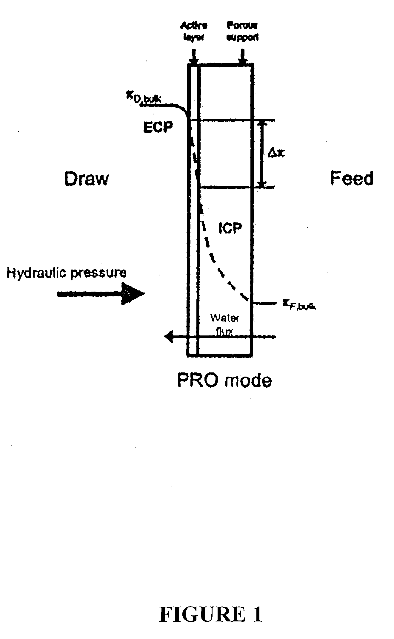
In cases where higher concentration streams are considered, higher hydraulic pressures may be used, but the process efficiency will suffer significantly from internal concentration polarization (ICP) which occurs in the support structure of the membrane used for the process.
However, the primary obstacle to a viable PRO process is poor membrane performance.
Previous investigations into PRO have found that membrane flux performance was too poor to make power generation a viable option.
Unfortunately, membranes currently in use are asymmetric in structure.
The porous support layer plays a significant, and often hindering, role

Method used


Image

  • Osmotic Heat Engine
  • Osmotic Heat Engine
  • Osmotic Heat Engine

Examples


example

[0054]Flux experiments were conducted in the laboratory to determine the viability of the osmotic heat engine process of the invention. Water flux must be high if the generation of power is to be efficient. Previous tests on flux using reverse osmosis membranes showed that the flux rarely exceeded minimum values (no more than 2-3 gallons per foot squared membrane area per day (gfd) and often much less than 1 gfd).

[0055]The inventors investigated a commercially available membrane which is tailored for osmotic processes and found flux to be much better. The data was taken with the NH3—CO2 draw solution on the active layer of the membrane. A deionized water feed was used to simulate osmotic heat engine conditions. Two temperatures were evaluated: 20° C. and 40° C., and the feed and draw solutions were maintained at identical temperatures for both series of tests. The results are shown in FIG. 3.

[0056]Two temperatures were tested over a range of osmotic pressures. Fluxes over 50 gfd wer...


PUM


Abstract

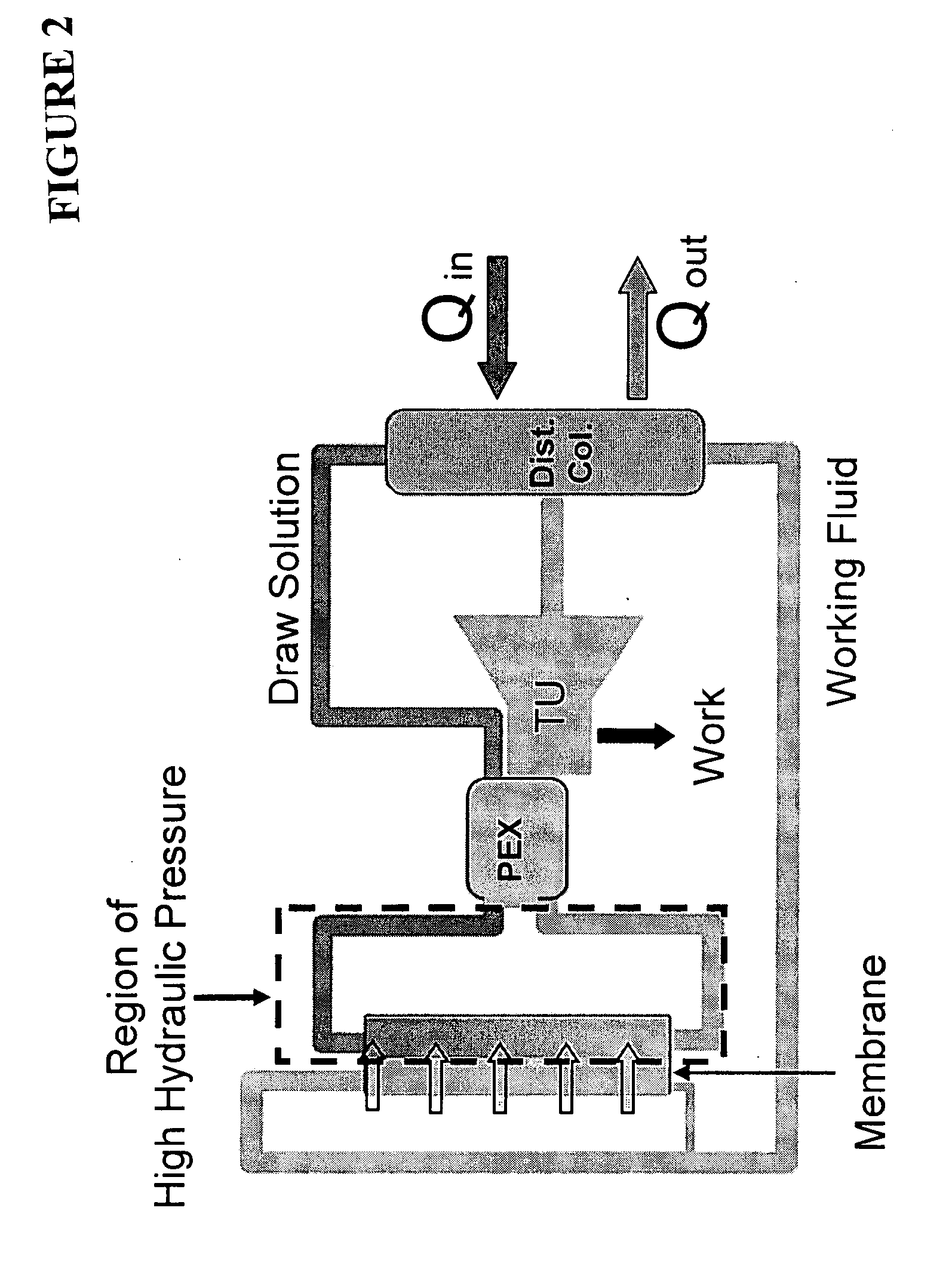
A method of converting thermal energy into mechanical work that uses a semi-permeable membrane to convert osmotic pressure into electrical power. A closed cycle pressure-retarded osmosis (PRO) process known as an osmotic heat engine (OHE) uses a concentrated ammonia-carbon dioxide draw solution to create high osmotic pressures which generate water flux through a semi-permeable membrane against a hydraulic pressure gradient. The depressurization of the increased draw solution volume in a turbine produces electrical power. The process is maintained in steady state operation through the separation of the diluted draw solution into a re-concentrated draw solution and deionized water working fluid, both for reuse in the osmotic heat engine.

Description

CROSS REFERENCE TO RELATED APPLICATIONS[0001]This application claims the benefit of U.S. Provisional Application No. 60 / 858,245, filed Nov. 9, 2006, the subject matter of which is herein incorporated by reference in its entirety.FIELD OF THE INVENTION[0002]The present invention relates to an osmotic heat engine for converting thermal energy into mechanical work that uses a semi-permeable membrane to convert osmotic pressure into electrical power.BACKGROUND OF THE INVENTION[0003]Increased global demand for energy, along with widening regulation of carbon dioxide emissions, have expanded interest in renewable energy sources and improved efficiencies in fuel use. However, an important restriction regarding the adoption of new fuels and energy technologies is the cost of power produced by these means. While subsidies and other forms of artificial support may assist in the introduction of these renewable energy sources, successful displacement of traditional fuels must necessarily be dri...

Claims


Application Information

Patent Timeline
IPC IPC(8): F03G7/00F03G7/06F03B17/00
CPCF03G7/005F03G7/04Y02E10/28Y02E10/34Y02E10/30B01D61/02F03B17/06F03G7/015F03G4/033F03G4/037Y02E10/20
Inventor MCGINNIS, ROBERT L.ELIMELECH, MENACHEMMCCUTCHEON, JEFFREY
Owner YALE UNIV
Why Eureka
Try Eureka