Membrane contactor systems for gas-liquid contact

a contactor system and membrane technology, applied in the field of membrane contactor systems, can solve the problems of increasing the cost of the system, affecting the utility of the system, and the amount of gas which has to be treated,

Inactive Publication Date: 2010-02-04
GENERAL ELECTRIC CO
View PDF12 Cites 29 Cited by
  • Summary
  • Abstract
  • Description
  • Claims
  • Application Information

AI Technical Summary

Problems solved by technology

Moreover, the amount of gas which has to be treated factors into the size of the apparatus.
Not only does this increase the cost of the system, but it can also impact the system's utility in applications where size and weight are a particularly expensive commodity, such as in offshore installations.
Membrane contactors, however,

Method used


Image

  • Membrane contactor systems for gas-liquid contact
  • Membrane contactor systems for gas-liquid contact
  • Membrane contactor systems for gas-liquid contact

Examples


Embodiment Construction

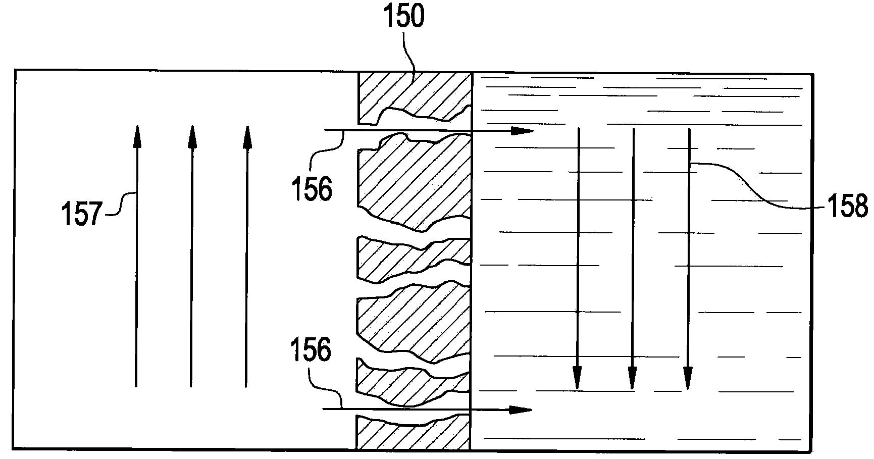
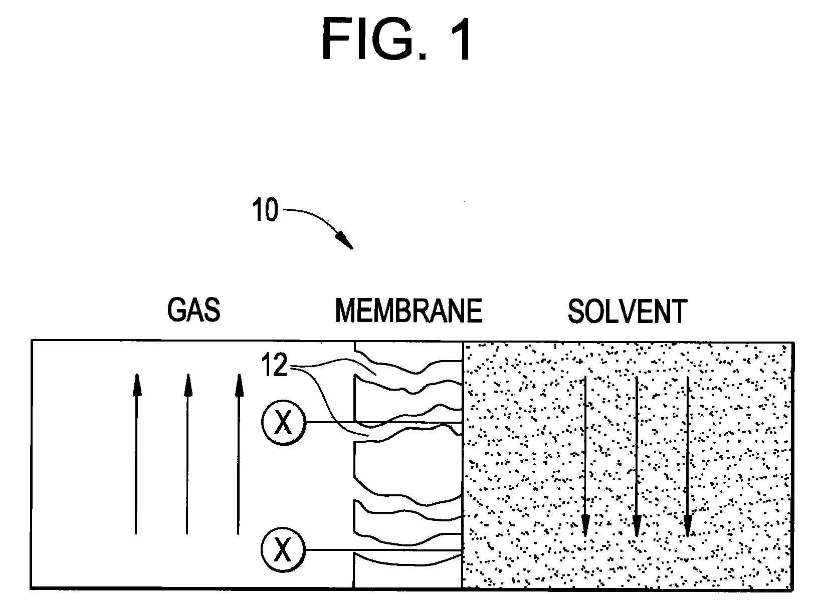
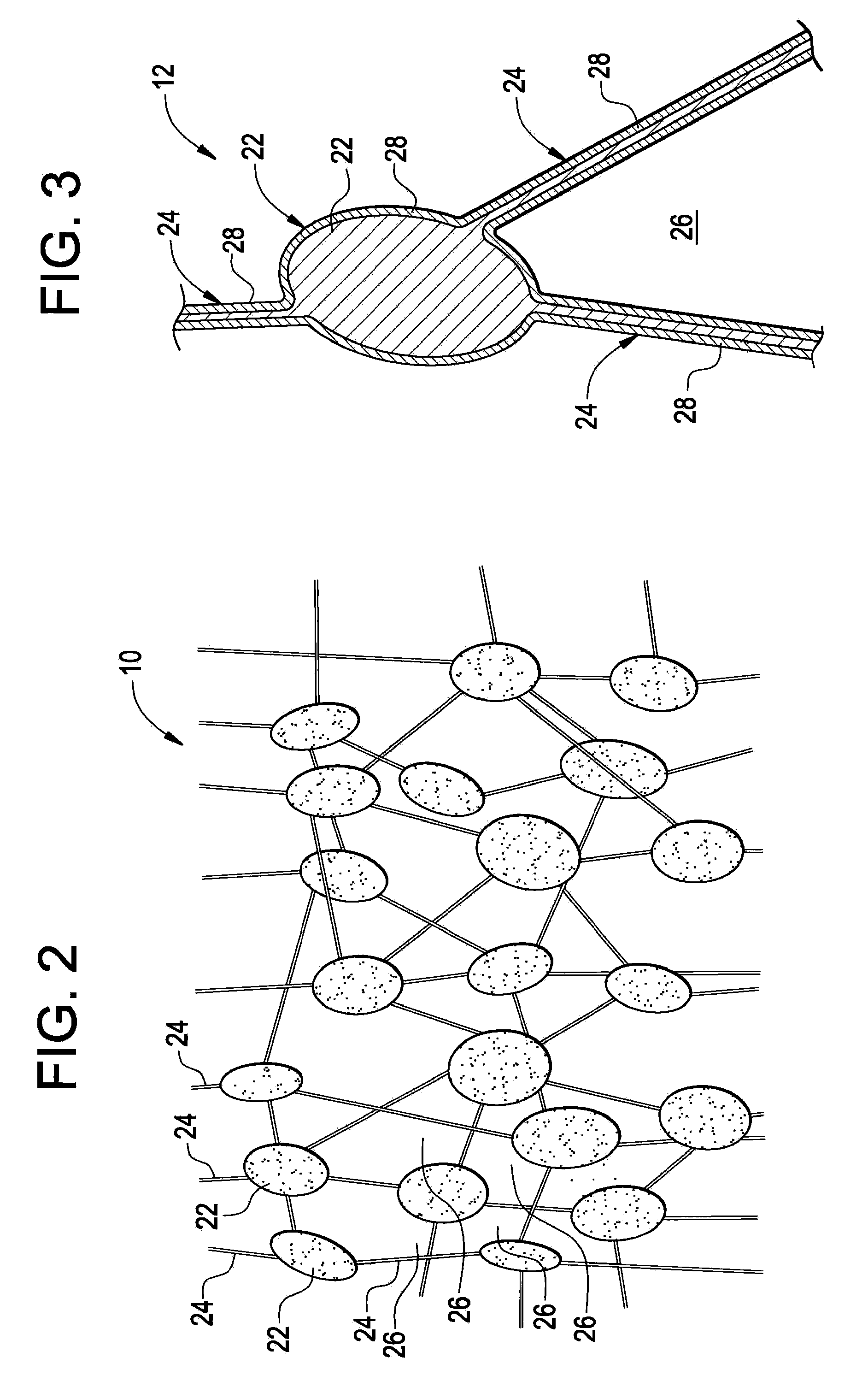
[0018]The membrane contactor systems described herein include an oleophobically-treated expanded polytetrafluoroethylene (PTFE) membrane. The oleophobic treatment on the expanded PTFE membrane can allow for the membrane contactor system to be effective in applications covering a wider range of liquids than current membrane contactors. The oleophobic treatment, moreover, can increase the operating life of the membrane in the contactor by reducing the amount of blockage of pores that can occur during use. The membrane contactor described herein can be disposed in any gas-liquid contacting application, such as, without limitation, carbon dioxide separation / removal, natural gas sweetening, oil degasification, and the like. In an exemplary embodiment, the membrane contactor system can replace current absorption units in a carbon dioxide (CO2) separation process. Employing the membrane contactor system instead of current separation technologies (e.g., packed bed scrubbers) for carbon diox...


PUM

PropertyMeasurementUnit
Oleophobicityaaaaaaaaaa

Abstract

A membrane contactor system for removing a component from a gas, comprising a housing defining a gas flow path; a microporous membrane positioned in the housing to allow the gas to flow across the membrane, wherein the membrane comprises a structure of nodes connected by fibrils in which surfaces of the structure of nodes and fibrils define a plurality of interconnecting pores extending through the microporous membrane, wherein the plurality of interconnecting pores are configured to allow the component to diffuse therethrough; and an oleophobic coating disposed on the microporous membrane to form a coated membrane and configured to provide oleophobicity to the coated membrane without blocking the plurality of interconnecting pores.

Description

BACKGROUND OF THE INVENTION[0001]This disclosure relates generally to membrane contactor systems for gas-liquid contacting in process industry and, more specifically, to membrane contactors utilizing an oleophobically-treated expanded polytetrafluoroethylene membrane.[0002]Systems for capturing and / or separating liquids and gases are desirable in a variety of applications. Exemplary gas-liquid contacting applications can include carbon dioxide separation, natural gas sweetening, degasification of oil, and the like. For example, the removal of carbon dioxide or other compounds from gases may be desirable or necessary for a number of reasons. If a gas is to be burned as fuel or emitted into the atmosphere as a waste flow, the removal of carbon dioxide from the gas is necessary in order to satisfy the carbon dioxide emission requirements which are set by air pollution control authorities. In natural gas, for instance, removing carbon dioxide (CO2) from the gas can satisfy sales specifi...

Claims


Application Information

Patent Timeline
IPC IPC(8): B01D53/92B01D71/06B01D53/22B01D71/36B01D53/62
CPCB01D53/228B01D53/229B01D53/62B01D53/77B01D61/246Y02C10/10B01D71/36B01D2251/80B01D2257/504B01D2325/38Y02C10/04B01D67/0088Y02A50/20Y02C20/40B01D53/22B01D53/78B01D65/08
Inventor BANSAL, VISHAL
Owner GENERAL ELECTRIC CO
Why Eureka
Try Eureka