
Starting Apparatus for a High-Pressure Discharge Lamp, and a High-Pressure Discharge Lamp with a Starting Apparatus

a technology of high-pressure discharge and starting apparatus, which is applied in the direction of electrical apparatus, gas discharge lamp details, light sources, etc., can solve the problems of unsuitable radiofrequency range operation, low frequency, and operation voltage of ac system

Inactive Publication Date: 2010-02-04
OSRAM GMBH
View PDF11 Cites 8 Cited by
  • Summary
  • Abstract
  • Description
  • Claims
  • Application Information

AI Technical Summary

Benefits of technology

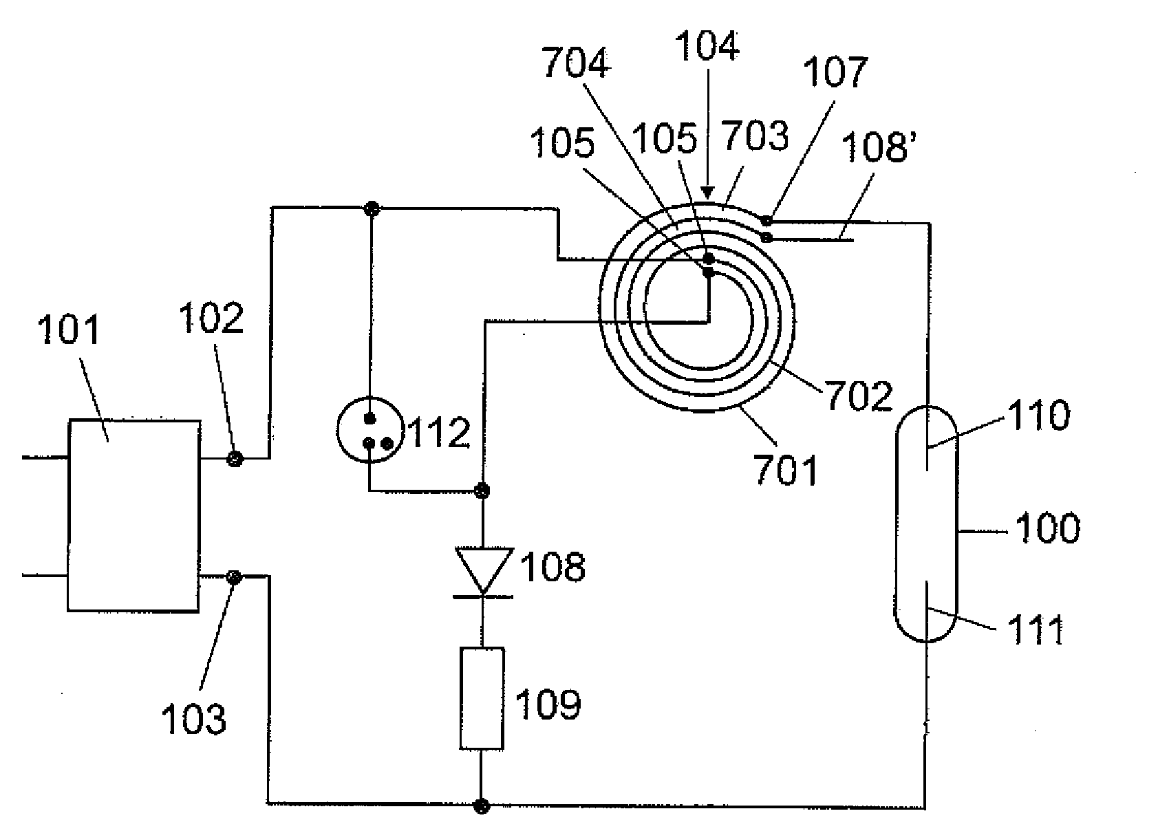
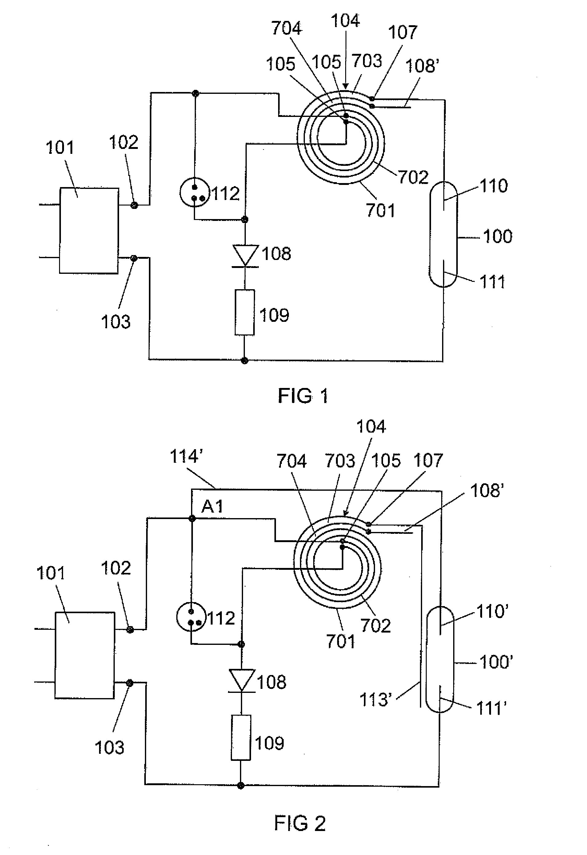
[0008]The starting apparatus according to the invention comprises a spiral line pulse generator and a charging circuit for charging the spiral line pulse generator, wherein, according to the invention, means for rectifying the charging current are provided in the charging circuit. The means for rectifying the charging current ensure that the spiral line pulse generator is charged during radiofrequency operation to a voltage which is high enough to be able to generate pulses with a sufficiently high amplitude which make it possible to start the gas discharge in the discharge lamp when the charging contacts of said spiral line pulse generator are short-circuited or when said spiral line pulse generator is discharged. In particular, the abovementioned means for rectifying the charging current ensure that the charging operation of the spiral line pulse generator can extend over a plurality of periods of the radiofrequency AC voltage in the case of radiofrequency operation of the starting apparatus and the discharge lamp. The means for rectifying the charging current of the spiral line pulse generator which are connected into the charging circuit therefore make it possible for the spiral line pulse generator to be capable of being used in radiofrequency operation of the high-pressure discharge lamp (for example at frequencies in the range of from 0.1 MHz to 5 MHz) as a starting pulse generator for generating the starting voltage pulses required for starting the gas discharge in the high-pressure discharge lamp. In addition to the cited frequency range, higher frequencies are also possible, for example operation of the discharge lamp in the ISM bands (Industrial Scientific Medical Bands) at 13.56 MHz and 27.12 MHz. In particular, the high operating frequency allows for operation of the discharge lamp above its acoustic resonances, which is of particular advantage since in this case negative effects as a result of acoustic resonances, such as flicker of the output light or reduced life of the lamp, for example, do not occur. Depending on the size of the lamp, the operating frequency should therefore be selected to be above approximately 300 kHz (for lamps with a high power, for example with a rated power of 250 W) up to approximately 2 MHz (for small lamps, for example with a rated power of 20 W). Advantageously, the means for rectifying the charging current of the spiral line pulse generator comprise at least one diode. Using the at least one diode makes it possible to ensure rectification of the charging current in a simple and inexpensive manner and to achieve a situation in which the charging of the spiral line pulse generator can extend over a plurality of periods of the radiofrequency AC voltage in order to enable sufficient charging of the spiral line pulse generator.
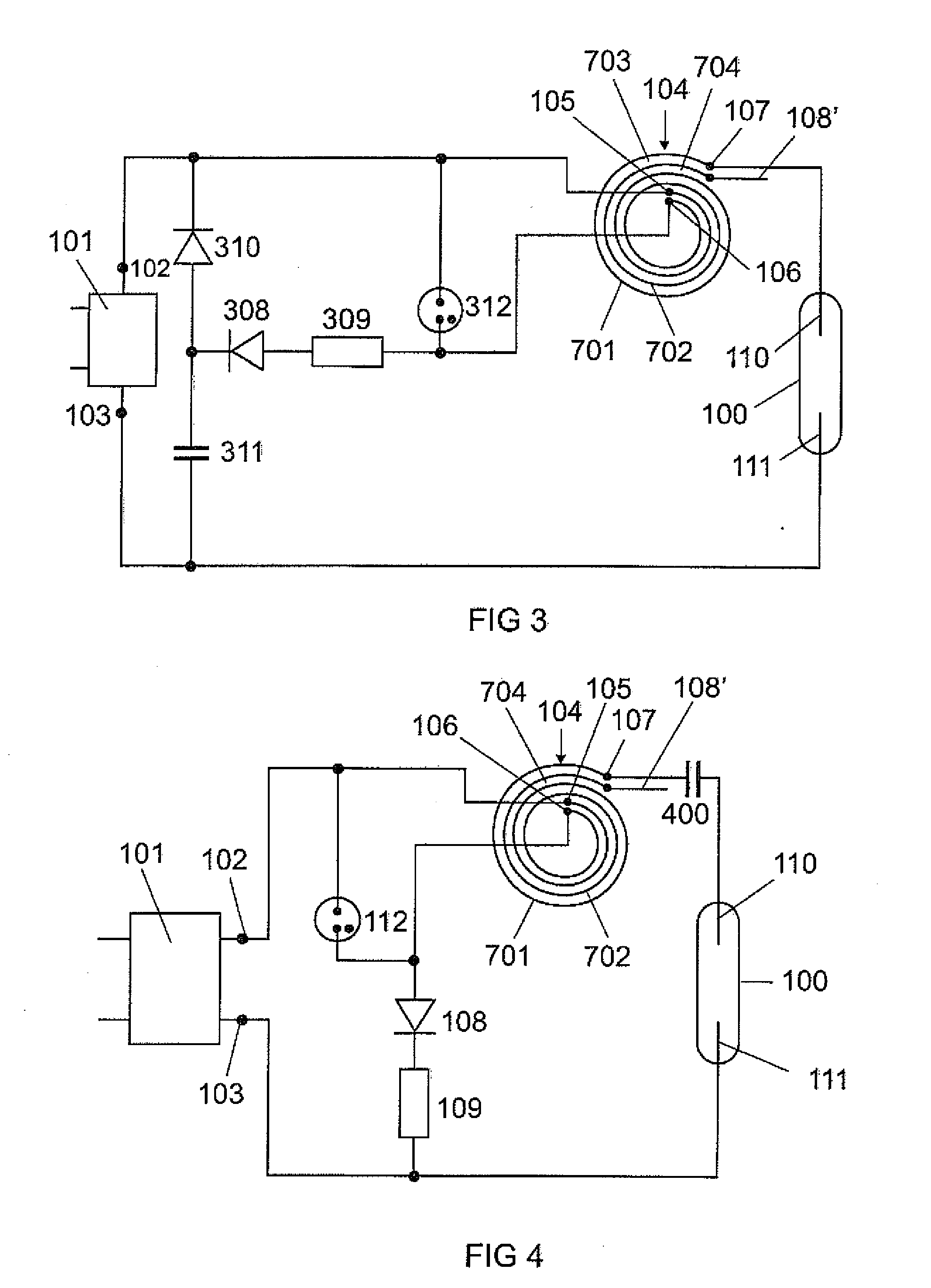
[0011]Preferably, at least one capacitor is connected in series with the spiral line pulse generator. This at least one capacitor provides a plurality of advantages. For the case in which the high voltage, generated by the spiral line pulse generator, is supplied to an auxiliary starting electrode, which is arranged externally on the discharge vessel, of the discharge lamp, the at least one capacitor suppresses diffusion of metal ions from the discharge medium to the discharge vessel wall. In particular, in the case of metal-halide high-pressure discharge lamps, the at least one capacitor prevents the diffusion of sodium ions to the discharge vessel wall and therefore contributes to a reduction in the sodium loss in the discharge medium. For the case in which the high voltage, generated by the spiral line pulse generator, is supplied to a gas discharge electrode, which is arranged in the discharge vessel, of the discharge lamp and, once the gas discharge in the lamp has been started, the radiofrequency lamp current flows via the spiral line pulse generator, the at least one capacitor allows for partial compensation of the inductance of the spiral line pulse generator. Owing to the partial compensation of the inductance of the spiral line pulse generator, the losses in the operating device of the lamp are reduced since the lower effective inductance of the spiral line pulse generator correspondingly results in reduced reactive powers. The at least one capacitor, which is connected in series with the spiral line pulse generator, also prevents a flow of direct current through the discharge lamp and therefore ensures that no segregation of the discharge plasma takes place. In addition, the at least one capacitor, which is connected in series with the spiral line pulse generator, forms a series resonant circuit with the spiral line pulse generator, which, owing to its characteristics by means of a slight frequency variation in the radiofrequency AC voltage provided by the AC voltage source, allows for regulation of the amplitude of the lamp current or of the electrical power injected into the lamp over a wide value range. In particular, the abovementioned series resonant circuit enables the so-called power startup in the case of a metal-halide high-pressure discharge lamp which acts as the light source in a vehicle headlamp. During this power startup, which takes place directly after starting of the gas discharge in the high-pressure discharge lamp, the high-pressure discharge lamp is operated at three to five times its rated power in order to achieve rapid vaporization of the metal halides in the discharge plasma.
[0012]In accordance with an exemplary embodiment of the invention, the spiral line pulse generator and the at least one capacitor, which is connected in series with the spiral line pulse generator, are formed as a common component part. This means that the functions of the spiral line pulse generator and of the at least one series-connected capacitor are realized by an integrated component part. This makes it possible to achieve a space-saving arrangement of these two components and both components can be accommodated, for example, in the lamp base or in the interior of the outer bulb of the lamp.

Problems solved by technology

One disadvantage with the abovedescribed starting apparatuses consists in the fact that they can only be operated on the AC system voltage, which has a comparatively low frequency, and are unsuitable for operation in the radiofrequency range, for example in the megahertz range.

Method used


Image

  • Starting Apparatus for a High-Pressure Discharge Lamp, and a High-Pressure Discharge Lamp with a Starting Apparatus
  • Starting Apparatus for a High-Pressure Discharge Lamp, and a High-Pressure Discharge Lamp with a Starting Apparatus
  • Starting Apparatus for a High-Pressure Discharge Lamp, and a High-Pressure Discharge Lamp with a Starting Apparatus

Examples


third exemplary embodiment

[0036]FIG. 3 schematically illustrates the circuit diagram of the starting apparatus according to the invention. This third exemplary embodiment differs from the first exemplary embodiment by virtue of the fact that a voltage doubling circuit 308, 310, 311 is arranged in the charging circuit of the spiral line pulse generator 104, which voltage doubling circuit provides the doubled, rectified output voltage of the ballast 101 at the inner terminals 105, 106 of the spiral line pulse generator 104. Identical component parts have therefore been provided with the same reference symbols in FIGS. 1 and 3. The voltage doubling circuit comprises the rectifier diodes 308, 310 and the capacitor 311. The voltage doubling circuit 308, 310, 311 is used to generate, from the radiofrequency output voltage which is provided at the terminals 102, 103 of the ballast 101, a DC voltage which is up to twice as high as the amplitude of the output voltage of the ballast 101 at the inner terminals 105, 106...

fifth exemplary embodiment

[0041]This function of the capacitor 800 is effective in all lamps with an auxiliary starting electrode, in particular those with an auxiliary starting electrode which is coupled capacitively or DC-coupled, irrespective of the fact that a lamp with a capacitively coupled auxiliary starting electrode is illustrated in FIG. 8. The mode of operation of the starting apparatus and the spiral line pulse generator 104 apart from the capacitor 800, is identical to the mode of operation of the abovedescribed second exemplary embodiment of the starting apparatus according to the invention.

[0042]The spiral line pulse generator 104 and the compensation capacitor 400 in accordance with the starting apparatus depicted in FIG. 4 can advantageously be formed as a common component part 500. Likewise, the spiral line pulse generator 104 and the capacitor 800 in accordance with the starting apparatus depicted in FIG. 8 can advantageously be formed as a common component part. However, the first mentio...


PUM


Abstract

A starting apparatus for a discharge lamp (100) comprising a spiral line pulse generator (104) and a charging circuit for charging the spiral line pulse generator, wherein means (108) for rectifying the charging current are arranged in the charging circuit.

Description

[0001]The invention relates to a starting apparatus for a discharge lamp which is equipped with a spiral line pulse generator, which generates the starting voltage required for starting the gas discharge in the discharge lamp.I. PRIOR ART[0002]Such a starting apparatus has been disclosed, for example, in U.S. Pat. No. 4,325,004 B1 and in U.S. Pat. No. 4,325,012 B1.[0003]U.S. Pat. No. 4,325,004 B1 describes a starting apparatus for a discharge lamp provided with an auxiliary starting electrode, wherein the starting apparatus has a spiral line pulse generator whose high-voltage terminal is connected to the auxiliary starting electrode. The discharge lamp and the starting apparatus are operated on the AC system voltage. A spark gap is connected in parallel with the contacts or terminals of the spiral line pulse generator which are arranged in the charging circuit, and this spark gap breaks down as soon as the charge on the spiral line pulse generator reaches the breakdown voltage of th...

Claims


Application Information

Patent Timeline
IPC IPC(8): H05B41/288
CPCH05B41/04H01J61/54H05B41/288
Inventor SIESSEGGER, BERNHARD
Owner OSRAM GMBH
Learn More