Railroad surveying and monitoring system

a technology for monitoring systems and railroad tracks, applied in the direction of instruments, using reradiation, ways, etc., can solve the problems of inaccurate surveying, poor accuracy of such data, labor-intensive conventional surveying practices, etc., and achieve data flexibility, easy configuration, and easy adaptation.

Inactive Publication Date: 2010-02-04
MARSHALL UNIV RES
View PDF11 Cites 100 Cited by
  • Summary
  • Abstract
  • Description
  • Claims
  • Application Information

AI Technical Summary

Benefits of technology

[0021]Another advantage of the system is its ability to be easily adapted to a number of mobile platforms such as track mounted vehicles like Sport Utility Vehicle (SUV) hy-rails, rail bikes or train engine/locomotives. This makes the present system flexible.
[0022]Aspects of the invention include its data flexibility and the fact that generated positional data is easily configured to be sent through a conventional TCP/IP network to a central computer, stored in a geographical information systems (GIS) database, displayed or otherwise provided to a user by appropriate means. This is achieved by the combination of using conventional HADGPS systems and standard NMEA data streams, wherein NMEA refers to the interface specifications between electronic equipment developed by the National Marine Electronics Association.
[0023]However, chief among the advantages of this invention is that is allows for rapid and accurate rail track modeling. Rail coordinate data generated by this invention is higher density (more points per foot) and collected faster than traditional surveying. Additionally, high position coordinate accuracies can be achieved by this system including a horizontal coordinate component of accuracy less than 1.5 cm and a vertical coordinate component of less than 2.5 cm. Further, the precise position coordinates are correlated with other sensor data including non-invasive subsurface technology such as ground penetrating radar (GPR), terrain conductivity data sensors, and optical cameras; all of which, can be easily displayed and configured into a usable database.
[0024]Equally important is that the coordinate data and other sensor data is generated and displayed in real time with this system or is stored f

Problems solved by technology

However, conventional surveying practices are labor intensive and produce mixed results, especially when used in areas of significant ground movement.
Because such conventional surveying systems require position on stable ground, any ground movement then results in the movement of the surveying monuments as well as the rails, thereby resulting in inaccurate surveying.
Equally well known are the limitations and poor accuracy of such data where there is loss of signal reception and inadequate sensor selection or configuration.
However, the art fails to address a mobile platform suitable for accurate, precise, and operationally flexibly equipped precision navigation and imaging sensors configured for real-time geo-referencing applications.
The art fails to identify a platform apparatus minimizing or accounting for these sources of error necessary for precision navigation and surveying in real-time applications.
It fails to address a mobile platform, suitable for accurate and precise surveying as well as operational flexibility.
This technology, however, is dependent upon lasers in combination with GPS systems, and fails to address platform movement, vibrations, location and selection of navigation and other sensors, antenna placement for reduction of data dropouts, using a survey controller for elevation offset, vehicle wandering and vehicle speed.
It fails to identify a platform apparatus minimizing or accounting for these sources of errors necessary for precision navigation and surveying in real time applications.
It fails to address a mobile platform, suitable for

Method used


Image

  • Railroad surveying and monitoring system
  • Railroad surveying and monitoring system
  • Railroad surveying and monitoring system

Examples


Embodiment Construction

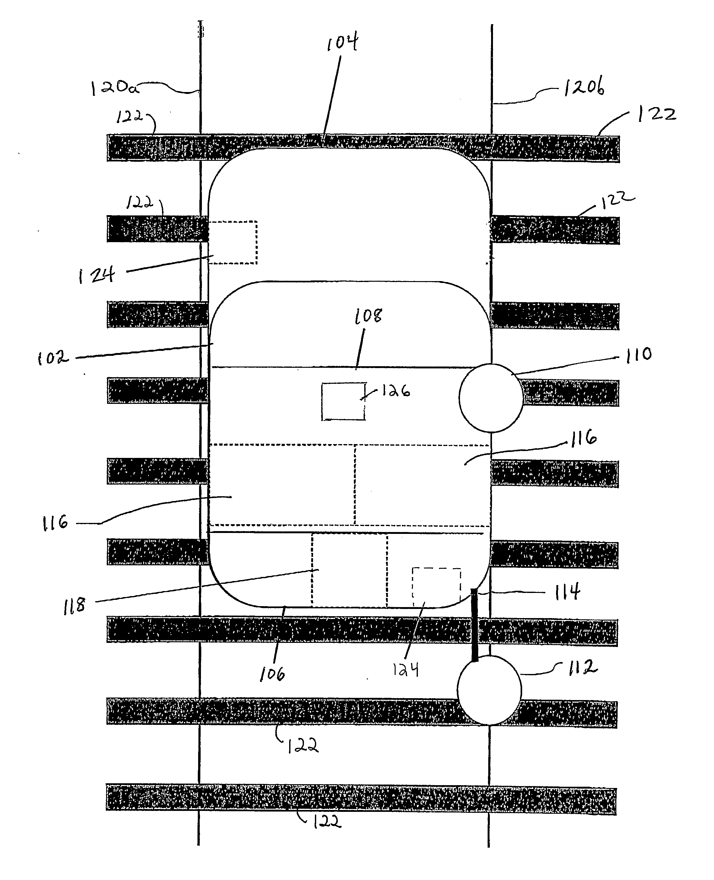
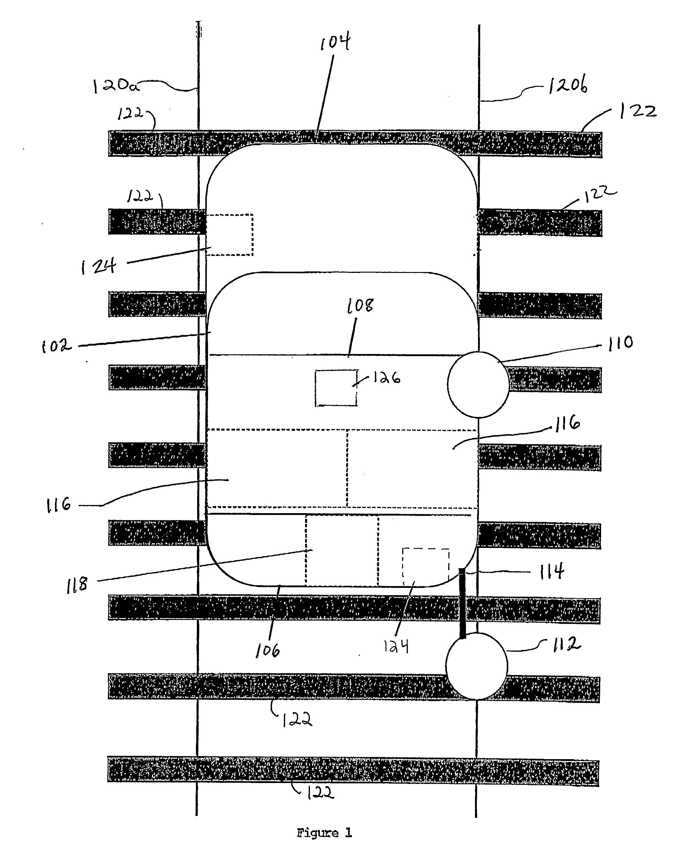
[0050]Preferred embodiments of the present invention herein described include an apparatus and method for multi-sensor railroad surveying and monitoring configured on a mobile platform. In one preferred embodiment as depicted in FIG. 1, is a mobile platform 102 having a roof rack 108. The front 104 and the rear 106 of the platform 102 are identified for convenience. A first rover 110 and a second rover 112 are attached to the platform 102 and in communication with a computer 126. In the preferred embodiment the computer 126 is attached to the mobile platform 102. The first rover 110 and the second rover 112 are positioned and aligned over the same track rail, e.g. rail 120b. For convenience purposes only, the present invention is described as surveying rail 120b. It would be readily apparent to one skilled in the art that the present invention can be applied to any rail, such as rail 120a. Also, the present invention is described in terms of a first and second rover 110, 112 for con...


PUM


Abstract

A Railroad Surveying and Monitoring System configured on a mobile platform for surveying, monitoring, and analyzing rail position and superstructure and terrain substructure of railroad tracks (20a,b) or other structures. The system employs two or more High Accuracy Differential Global Positioning System devices (110,112), ground penetrating radar devices (116), terrain conductivity instruments (118), optical cameras (124), and data receivers and processors (126), which in turn process, display, and store the data in a usable database. Precise coordinate data generated from a High Accuracy Global Positioning System provides both location data for subsurface sensors and surface sensors and rail position coordinates to monitor track displacements during track inspection in real time.

Description

CROSS-REFERENCE TO RELATED APPLICATIONS[0001]This application claims the benefit of U.S. Provisional Application No. 60 / 509,212 filed Oct. 6, 2003, and U.S. Provisional Application No. 60 / 509,213 filed Oct. 6, 2003.BACKGROUND OF THE INVENTION[0002]1. Field of Invention[0003]This invention pertains to a mobile railroad track surveying and monitoring apparatus and method, and more particularly, to a system employing High Accuracy Differential Global Positioning System receivers linkable with other non-invasive sensors for rail track superstructure and substructure surveying and monitoring. The invention is capable of modeling rail track movement, rail track vectors, rail track alignment, and subsurface conditions. The apparatus includes a mobile platform and surveying components situated for measuring accurate position data for rail alignment, rail surveying, and displacement trajectories of rail, as well as for collecting subsurface condition data. Means are additionally provided to ...

Claims


Application Information

Patent Timeline
IPC IPC(8): G06F15/00G01S5/14G01S13/00B61K9/08G01B5/20G01SG01S5/10G01S13/86G01S13/88G01S19/54
CPCB61K9/08B61L23/047E01B37/00G01S13/867G01S13/885G01S19/54G01S13/86
Inventor SZWILSKI, ANTHONY B.BEGLEY, RICHARD D.
Owner MARSHALL UNIV RES
Why Eureka
Try Eureka