Cooling Systems and Electronic Apparatus

a technology of electronic equipment and cooling system, which is applied in the direction of domestic cooling equipment, electric equipment casings/cabinets/drawers, instruments, etc., can solve the problems of complicated apparatus configuration and inability to introduce external air, and achieve efficient cooling of an electronic equipment group, low noise, and reduced temperature variation among electronic equipment installed in the data center

Inactive Publication Date: 2010-02-04
HITACHI LTD
View PDF13 Cites 92 Cited by
  • Summary
  • Abstract
  • Description
  • Claims
  • Application Information

AI Technical Summary

Benefits of technology

[0027]According to the present invention, temperature variation among the electronic apparatuses installed in the data center is reduced, efficient cooling of an electronic apparatus group and the electronic apparatus with low noise can be provided.

Problems solved by technology

In each of the prior arts according to JP-A-2006-208000 and JP-A-2007-505285, a sensor is required to be installed in each place in a data center and a controller for determining a situation is required to be separately provided, which complicates the apparatus configuration.
Thus, if the humidity is not in the proper range even when the external air temperature is sufficiently low, external air cannot be introduced.

Method used


Image

  • Cooling Systems and Electronic Apparatus
  • Cooling Systems and Electronic Apparatus
  • Cooling Systems and Electronic Apparatus

Examples


embodiment 1

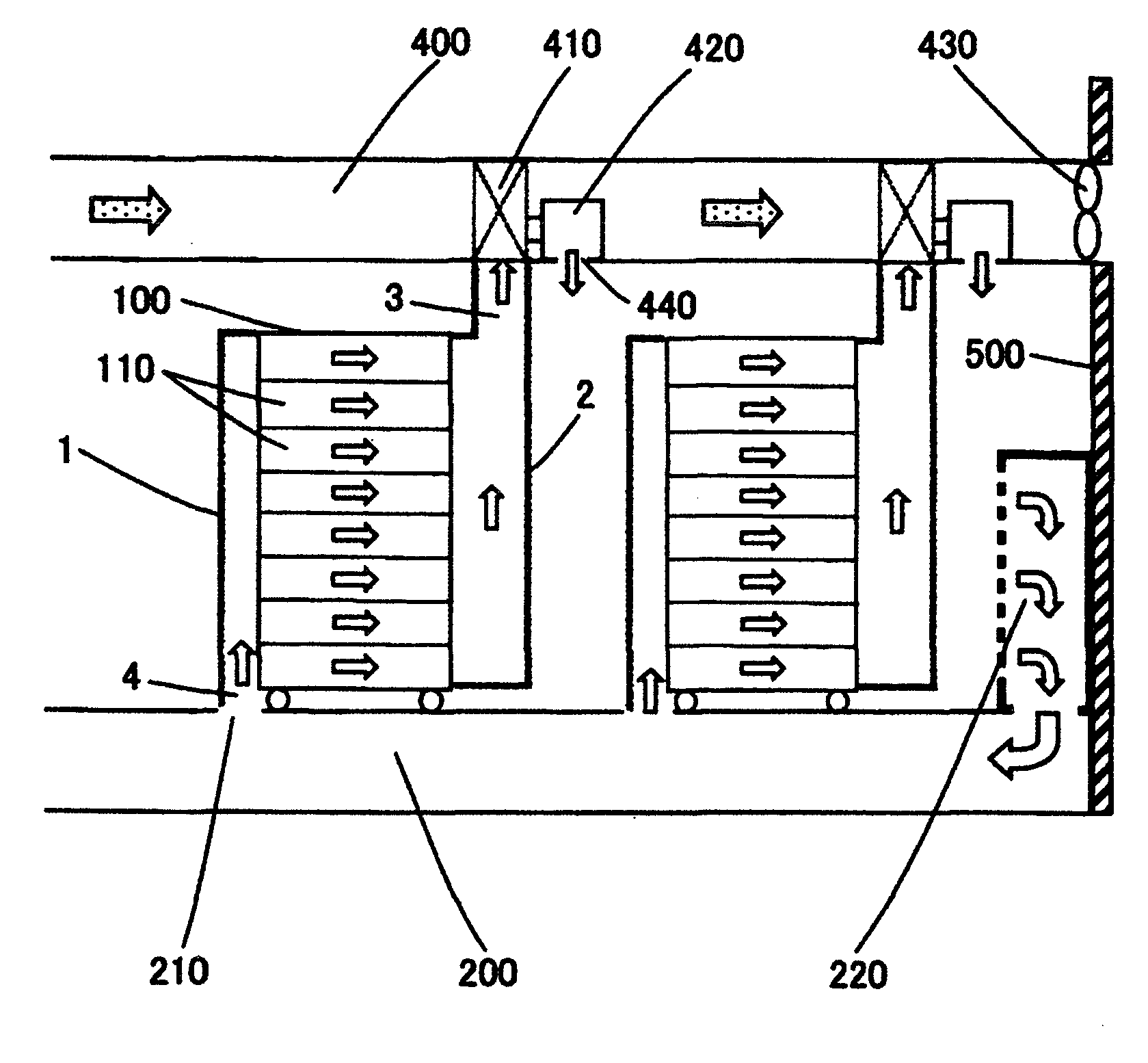
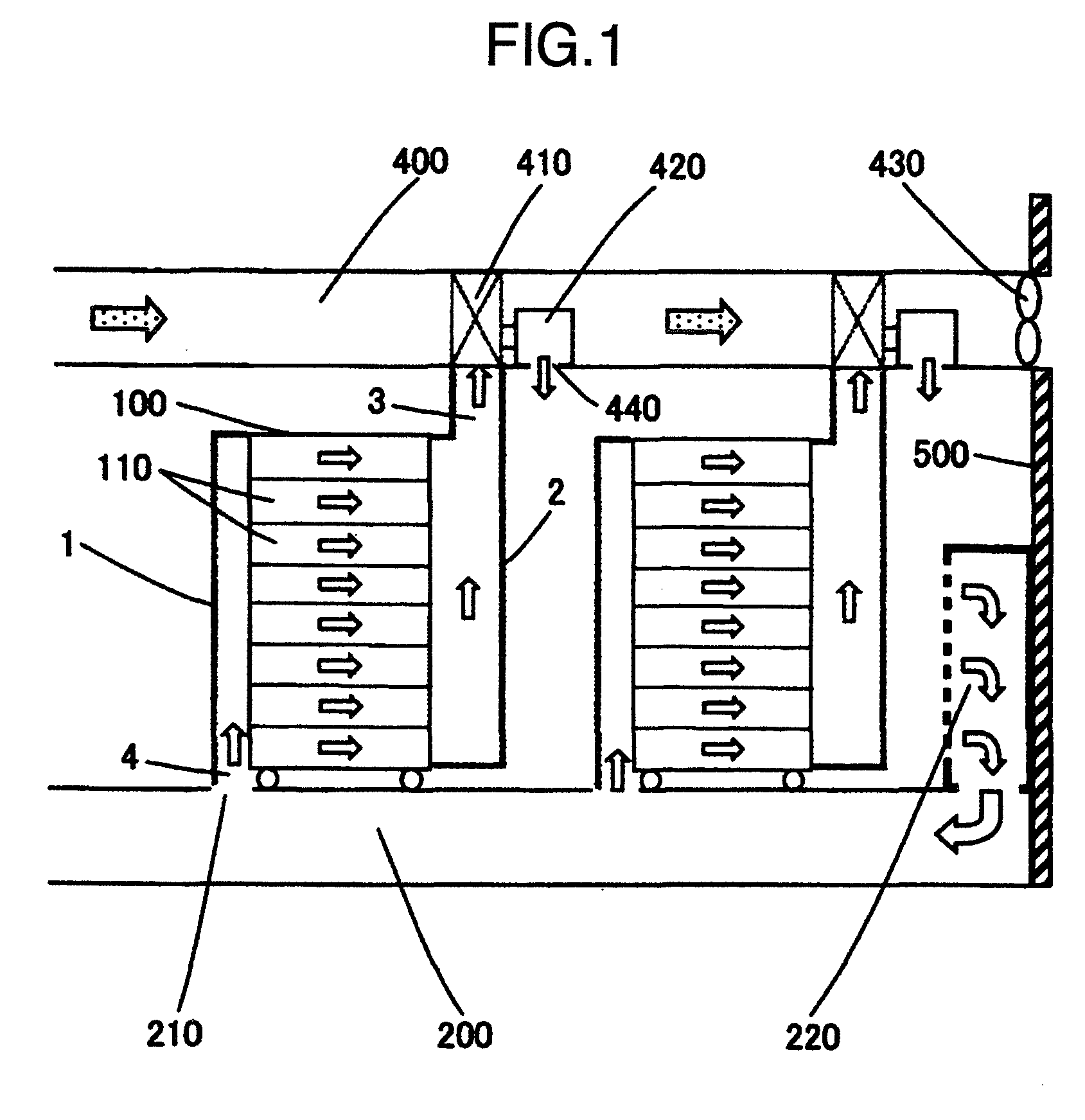
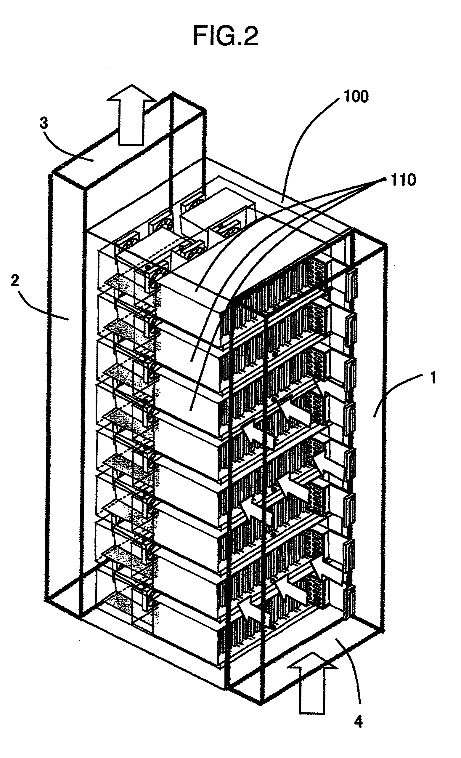
[0040]FIG. 1 is a schematic configuration view of a cooling system including one embodiment of the present invention. FIG. 2 is a perspective view of an electronic apparatus including the present embodiment.

[0041]In FIGS. 1 and 2, a cooling system of the present embodiment is configured by an electronics rack 100, an air conditioning area at below the floor level 200, an air conditioner 220, a ceiling air duct 400 and the like. The electronics rack 100 is configured by electronic equipment 110 in multiple layers installed in the rack. In the present embodiment, a 19-inch standard rack is adopted, and a plurality of fans not illustrated are provided in the electronic equipment 110 in the multiple layers installed in the rack. By the fans, cooling air is taken in from the front side of the rack and is exhausted from the rear side. Further, in the present embodiment, a front cover 1 is provided at the front surface of the electronics rack 100, and a back cover 2 is provided at the rear...

embodiment 2

[0050]FIG. 3 is a schematic configuration view of a cooling system including a second embodiment of the present invention.

[0051]In FIG. 3, the cooling system is also configured by the electronics rack 100, the air conditioning area at below the floor level 200, the air conditioner 220, the ceiling air duct 400 and the like in the present embodiment. In the present embodiment, the flow path is divided into two flow paths that are the ceiling air duct 400 in which the indoor side air flows, and a ceiling air duct 400′ in which external air flows, and the heat exchanger 410 is provided between the two flow paths. In the case of FIG. 3, external air flows in from the lower right side of the wall 500, and is exhausted from the upper right side of the wall 500. The heat exchanger 410 is for gas, with one flow path being connected to the external air flowing inside the ceiling air duct 400′, and with the other flow path being connected to the indoor air flowing in the ceiling air duct 400....

embodiment 3

[0059]A third embodiment of the present invention is shown in FIG. 4.

[0060]FIG. 4 is a schematic general view of a cooling system in the present embodiment.

[0061]In FIG. 4, the cooling system is also configured by the electronics rack 100, the air conditioning area at below the floor level 200, the air conditioner 220, the ceiling air duct 400 and the like in the present embodiment. Further, the ceiling air duct 400 is divided into two flow paths that are an indoor side air flow 400a, and an external air flow 400a′, and the heat exchanger 410 is provided between the two flow paths.

[0062]In the present embodiment, a set of an ANC (Active Noise Control) device is incorporated in the vicinity of the ceiling blowing out opening 440 of the ceiling air duct 400 at the indoor air side. The ANC device of the present embodiment is configured by an error sensor 330, a noise sensor 320, a speaker 310, and an active noise controller 300. The ANC device calculates a signal in an opposite phase f...


PUM


Abstract

Temperature variation among electronic apparatuses installed in the data center is reduced, enhancement in reliability of the electronic apparatuses, and increase in service life are achieved, and efficient cooling of an electronic apparatus group is realized. Further, an electronic apparatus with low noise is provided. A front cover is provided on a front surface of an electronic apparatus, and a back cover is provided on a rear surface of it. A supplied air opening is formed at a lower side of the front cover, and an exhaust air opening is formed at an upper side of the back cover. The supplied air opening is connected to a blowing in opening from below the floor level, and the exhaust air opening is connected to a ceiling air duct. The ceiling air duct is provided with a heat exchanger, and indirect heat exchange is performed with external air.

Description

BACKGROUND OF THE INVENTION[0001]The present invention relates to a cooling system and electronic apparatus in which ambient temperature of a data center containing therein the electronic apparatus is adjusted.[0002]An electronic apparatus such as a disk array apparatus is configured by being loaded with a number of magnetic or optical disk drives inside a casing to enhance reliability of data storage. These disk array apparatuses are operated by management software by being connected with a high-speed special network line such as an optical line, and used as a SAN (Storage Area Network), NAS (Network Attached Storage), or a single RAID (Redundant Array of Inexpensive Disks) disk apparatus.[0003]The main heat generation sources of the disk drives loaded on these disk array apparatuses are control electronic components such as a drive motor, an actuator, and an LSI. Heat of them is cooled by cooling air which is supplied by the cooling fan installed in the disk array casing. When the...

Claims


Application Information

Patent Timeline
Patent Type & Authority Applications(United States)
IPC IPC(8): H05K7/20F28D15/00
CPCH05K7/20745
Inventor MATSUSHIMA, HITOSHIFUKUDA, HIROSHINAKAJIMA, TADAKATSU
Owner HITACHI LTD
Why Eureka
Try Eureka