Scrambled multicarrier transmission

a multi-carrier transmission and scramble technology, applied in the field of radio communication systems, can solve the problems of interference mitigation processing, no information about the interferencer is usually recovered/reconstructed, and hardly convenient solution

Inactive Publication Date: 2010-02-04
TELECOM ITALIA SPA
View PDF4 Cites 112 Cited by
  • Summary
  • Abstract
  • Description
  • Claims
  • Application Information

AI Technical Summary

Benefits of technology

[0022]The arrangement described herein can be used advantageously in systems such as OFDM systems that adopt frequency interleaving and concatenated channel coding. Moreover, information about the interferers can be obtained at the receiver thus permitting both interference mitigation processing at the receiver and closed-loop, receiver driven pre-equalization at the transmitter.

Problems solved by technology

Despite certain merits in terms of improved throughput and possible improvement in the channel estimation accuracy, the Applicant has observed that prior art arrangements as represented by WO-A-2005 / 086446 have a number of inherent weaknesses.
In real-life OFDM systems, symbol timing recovery can become critical in the low Signal-to-Noise Ratio (SNR) area, and cannot always rely on GI autocorrelation: especially in those systems where the Guard Interval is relatively short, accurate synchronization could in fact be obtained by resorting to a training sequence (not subject to scrambling), but this solution would hardly be convenient in comparison with arranging the system so that the signal is scrambled in its entirety;prior art arrangements as taught in WO-A-2005 / 086446 are useful primarily when an interfering signal with coloured spectrum is “whitened” at the receiver.
However, OFDM systems usually adopt frequency interleaving and concatenated channel coding, so that interference whitening may not always lead to performance improvement; andin receivers according to the prior art, no information about the interferers is usually recovered / reconstructed, and no interference mitigation processing is performed.

Method used


Image

  • Scrambled multicarrier transmission
  • Scrambled multicarrier transmission
  • Scrambled multicarrier transmission

Examples


Embodiment Construction

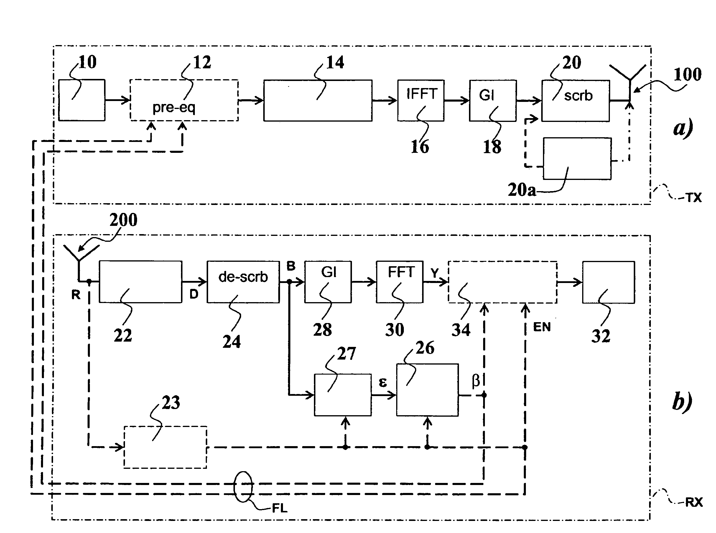
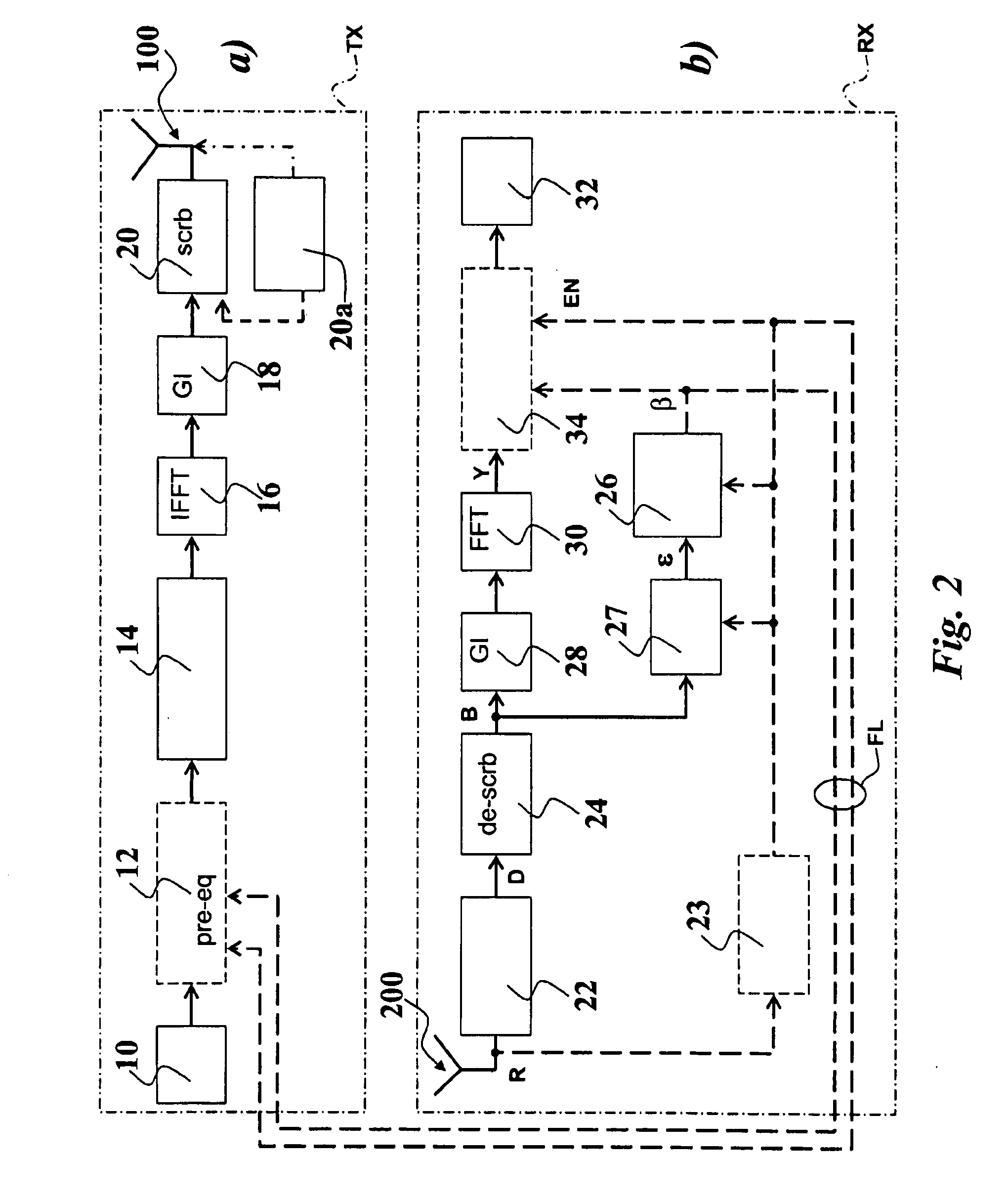
[0029]The exemplary transmission system described herein is an OFDM multi-carrier transmission system equipped with a SISO (Single-Input Single-Output) or MIMO (Multiple-Input Multiple-Output) antenna system. For generality, the system will be assumed to operate with N subcarriers, MT transmit (TX) antennas (designated collectively as 100 in both FIGS. 2 and 3) and MR receive (RX) antennas (designated collectively as 200 in both FIGS. 2 and 3).

[0030]The data part of the signal at the m-th TX antennas can be expressed as:

xm(t)=1Nsm(t)∑n=0N-1Xm(n)j2πnt / N,m=1…MT(1)

[0031]where sm is a complex scrambling sequence. This sequence can be specific for the m-th TX antenna of a given BTS or be cell-specific or sector-specific. The sequence can have a time period equal to one or more OFDM symbols (in practical implementations could be as long as a Transmission Time Interval TTI) and will typically have a unitary module. Certain points on the periodicity of the scrambling sequence will be furthe...


PUM


Abstract

Signals (typically in the form of OFDM signals) are transmitted between one or more transmitting antennas and one or more receiving antennas. The signals transmitted are subject to addition of a guard interval before scrambling in the time domain, while the signals received are subject to removal of the guard interval after scrambling in the time domain. Preferably time-scrambling of the OFDM signal being transmitted occurs after IFFT processing and guard interval insertion, while time de-scrambling of the signal being received occurs before both guard interval removal and FFT processing. Optionally, unscrambled pilot symbols (e.g. in the form of a training sequence), can be present at regular intervals inside the signal structure. At the receiver, equalization is carried out preferably in the frequency domain.

Description

FIELD OF THE INVENTION[0001]The invention relates to radio communication systems and more specifically to digital multicarrier communication systems.DESCRIPTION OF THE RELATED ART[0002]Cellular phone systems and portable / mobile terminals using cellular transmission techniques have evolved over the years from analogue narrowband transmission (also known as 1st generation), to digital narrowband transmission (2nd generation or 2G) and on to digital broadband transmission (3rd generation or 3G). Further evolution towards still higher data rates can be based on improvements in the spectral efficiency of the transmission system. However, given the inevitable limits on spectral efficiency, an increase in the transmission bandwidth is foreseen for future generations of cellular phones. Such an increase in the transmission bandwidth typically entails an increase in the receiver circuit complexity, which depends i.a. on the type of modulation and multiplexing adopted. For instance, 3G system...

Claims


Application Information

Patent Timeline
Patent Type & Authority Applications(United States)
IPC IPC(8): H04L27/28H04B7/02H03H7/30H04L27/00H03D1/00H04L9/00
CPCH04L25/03343H04L25/03866H04L25/03159H04L27/261H04L2025/03414H04L27/2607
Inventor PRIOTTI, PAOLO
Owner TELECOM ITALIA SPA
Why Eureka
Try Eureka