Glass sheet defect detection device, glass sheet manufacturing method, glass sheet, glass sheet quality judging device, and glass sheet inspection method

a defect detection and quality judging technology, applied in the direction of optical apparatus testing, manufacturing tools, instruments, etc., can solve the problems of difficult to completely suppress the generation of defects, such as abnormalities of surface quality, and generate defects in glass sheets. , to achieve the effect of high speed defect inspection, high precision and sufficient information on defects

Inactive Publication Date: 2010-02-04
NIPPON ELECTRIC GLASS CO LTD
View PDF6 Cites 20 Cited by
  • Summary
  • Abstract
  • Description
  • Claims
  • Application Information

AI Technical Summary

Benefits of technology

[0048](1) As described above, in the glass sheet defect detection device of the present invention, a glass sheet, a light source, and a light reception device are placed so that the light transparent surface of a glass sheet is inclined with respect to a light axis, and the focal length of a lens system of the light reception device is set so as to be smaller than the distance from a light reception element of the light reception device to the class sheet on the light axis. Therefore, the device can obtain sufficient information on defects even with respect to a glass sheet with a particularly small thickness, and can realize a high speed defect inspection with a high precision owing to less noise mixed in the light reception device.
[0049](2) Further, sites to be inspected of a glass sheet are scanned with a light ray from a light source in a direction crossing the direction in which the defects are continued, whereby the detection ability with a high precision can be exhibited regarding the defects such as minute striae, invisible streaks, continued foreign matters and bubbles, and a surface wave.
[0050](3) Further, by providing a storage device for storing information on a light ray received by a light reception device and a data display portion for displaying the information on a display, a device excellent in reusability of information and in visibility is obtained, and the device exhibits a remarkably great effect in the case where a quick action is requested as an abnormal detection means in the step and when problems of the manufacturing method are analyzed.
[0051](4) According to the glass sheet manufacturing method of the present invention, the defects on the surface of and / or inside a glass sheet formed by a forming device after heat-melting and followed by cooling are inspected using the glass sheet defect detection device and the quality is judged. Therefore, the quality of a glass sheet as a product can be judged at an early stage, which can enhance a production efficiency.
[0052](5) The glass sheet of the present invention is made of alkalifree glass and has a thickness of 0.7 mm or less and a maximum defect size of Tess than 0.1 μm. Therefore, the glass sheet is suitable as the one to be mounted on a large image display device such as a liquid crystal display device of 40 inches or more, which is required to have a high definition. The glass sheet is a glass material having suitable excellent homogeneity.
[0053](6) The glass sheet quality judging device of the present invention includes a measurement means for irradiating a glass sheet with a light ray from a light source and receiving the light ray from the glass sheet by a light reception device, a chart acquiring means for subjecting a brightness profile or an image obtained by the measurement means to Fourier transformation or wavelet transformation to obtain a processing result chart, and an algorithm processing system for evaluating the defects of the glass sheet based on the processing result chart to judge the quality. Therefore, the quality can be judged easily and exactly regarding the defects of the glass sheet, and further, the manufacturing system in accordance with the required quality can be established easily by changing the reference value of the defects of the processing result chart if required.

Problems solved by technology

At this time, due to various causes such as an insufficiently molten glass material, unintended contamination of foreign matters in a course of manufacturing, aging of a forming device, and inconveniences of temporary forming conditions, a defect such as abnormality of a surface quality may be generated in a glass sheet.
However, it is difficult to completely suppress the generation of the defects, and even when the generation of defects can be suppressed to some degree, if there is no technology of distinguishing a glass sheet with a defect clearly, defective products that are supposed to be judged as failed products may be mixed with glass sheets judged to be of good quality.

Method used


Image

  • Glass sheet defect detection device, glass sheet manufacturing method, glass sheet, glass sheet quality judging device, and glass sheet inspection method
  • Glass sheet defect detection device, glass sheet manufacturing method, glass sheet, glass sheet quality judging device, and glass sheet inspection method
  • Glass sheet defect detection device, glass sheet manufacturing method, glass sheet, glass sheet quality judging device, and glass sheet inspection method

Examples


example 1

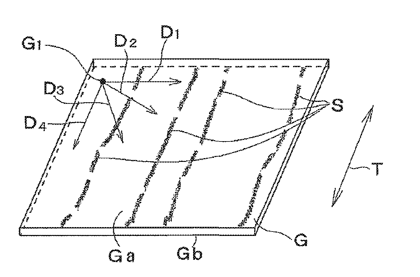
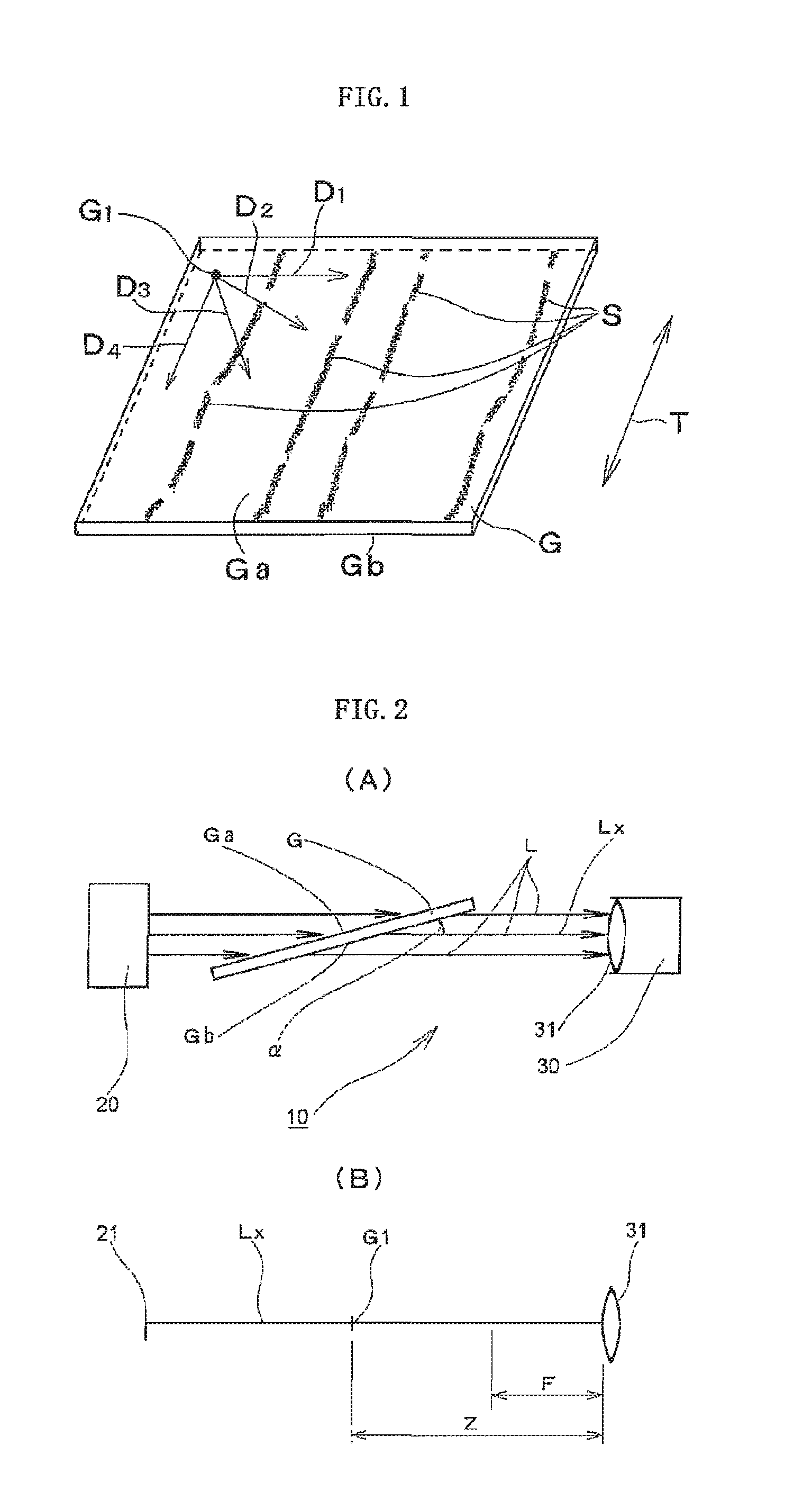
[0056]FIGS. 2 (A) and 2 (B) conceptually illustrate a glass sheet defect detection device 10 according to Example 1. The glass sheet defect detection device 10 includes a light source 20 and a light reception device 30 which are placed at opposed positions so as to sandwich a glass sheet G. The glass sheet G has light-transparent surfaces Ga, Gb opposed to each other in a thickness direction, and is placed between the light source 20 and the light reception device 30 so that the light-transparent surfaces Ga, Gb are inclined by a predetermined angle α with respect to a light axis Lx (line connecting centers of a series of optical elements constituting an optical system from the light source 20 to the light reception device 30) of the optical system of the glass sheet defect detection device 10. Further, the light reception device 30 and the glass sheet G are placed in such a positional relationship that a focal length F of a lens system 31 of the light reception device 30 is smaller...

example 2

[0078]Next, a glass sheet defect detection device 11 according to Example 2 is described specifically with reference to FIG. 6. The glass sheet detection device 11 is configured so as to measure, for example, a thin glass sheet G with a width of 1500 mm and a thickness of 0.65 mm to be mounted on a TFT liquid crystal display device continuously with a space saved. FIG. 6 schematically illustrates the configurations of main portions of the glass sheet defect detection device 11 and illustrates that the glass sheet G is extracted continuously downward by heat-resistant rolls (not shown) after being formed from a glass melting furnace from an upper side to a lower side. W in the figure indicates the movement direction of the glass sheet G.

[0079]The glass sheet defect detection device 11 includes a light source 20, and a light reception device 30a, and a reflective mirror 40 placed so as to sandwich the glass sheet G. For example, a metal halide lamp is used as the light source 20, and ...

example 3

[0082]Further, FIG. 7 illustrates a conceptual view regarding a glass sheet defect detection device with another configuration. In the glass sheet defect detection device, the distance from the light source 20 to the position G1 of the glass sheet G is set to be 1000 mm, and the distance from the position G1 of the glass sheet G to the solid imaging element of the light reception device 30a is set to be 1000 mm on the light axis Lx. The focal length of the lens system of the light reception device 30a is 700 mm. Thus, on the light axis Lx, the focal length 700 mm of the lens system of the light reception device 30a is smaller than the distance 1000 mm from the light reception device 30a to the position G1 of the glass sheet G. Further, the angle αformed by the light-transparent surfaces Ga, Gb of the glass sheet G and the light axis Lx is 20°.

[0083]The glass sheet defect detection device is configured so as to perform measurement when moving the cut glass sheets G one by one. The gl...


PUM

PropertyMeasurementUnit
defect sizeaaaaaaaaaa
thicknessaaaaaaaaaa
optical path lengthaaaaaaaaaa

Abstract

A glass sheet defect detection device includes a light source and a light reception device which are placed at opposed positions so as to sandwich a glass sheet. The glass sheet has light-transparent surfaces opposed to each other in a thickness direction. The glass sheet is placed between the light source and the light reception device so that the light-transparent surfaces are inclined with respect to a light axis of an optical system of the glass sheet defect detection device at a predetermined angle. Moreover, the light reception device and the glass sheet are placed in such a positional, relationship that a focal length of a lens system of the light reception device is smaller than a distance from a light reception element of the light reception device and the glass sheet.

Description

TECHNICAL FIELD[0001]The present invention relates to a defect detection device of detecting defects of a glass sheet formed from molten glass, in particular, a glass sheet mounted on a liquid crystal display device or a plasma display, a manufacturing method for a glass sheet using the defect detection device, a glass sheet obtained by the manufacturing method, and a quality judging device of evaluating defects of a glass sheet to judge the quality thereof.BACKGROUND ART[0002]Along with remarkable advancement of a display device technology, technologies related to image display devices of various kinds of systems such as a liquid crystal display and a plasma display have been progressed significantly. Particularly, in large-size image display devices and the like in which a high-definition display is realized, high-level technical innovation is in progress in order to reduce a production cost and enhance an image quality. A glass sheet to be mounted on such various kinds of devices...

Claims


Application Information

Patent Timeline
Patent Type & Authority Applications(United States)
IPC IPC(8): B32B17/00G01N21/896G06F19/00C03B17/06G01N21/958
CPCG01M11/081Y10T428/1045G02F2001/133302G01N21/896C09K2323/033G02F1/133302G01B11/30G01M11/00G01N21/958G02F1/13
Inventor SUIZU, HIDEMINISHIMURA, YASUHIROIWATA, MASAKAZU
Owner NIPPON ELECTRIC GLASS CO LTD
Why Eureka
Try Eureka