

Friction- and wear-reducing coating
a friction- and wear-reducing coating technology, applied in the field of friction-reducing coatings, can solve the problems of shortened service life, wear, and wear of the movable component, and achieve the effects of excellent tribological properties and performance, excellent hardness and anti-wear performance, and reduced friction and wear
- Summary
- Abstract
- Description
- Claims
- Application Information
AI Technical Summary
Benefits of technology
Problems solved by technology
Method used
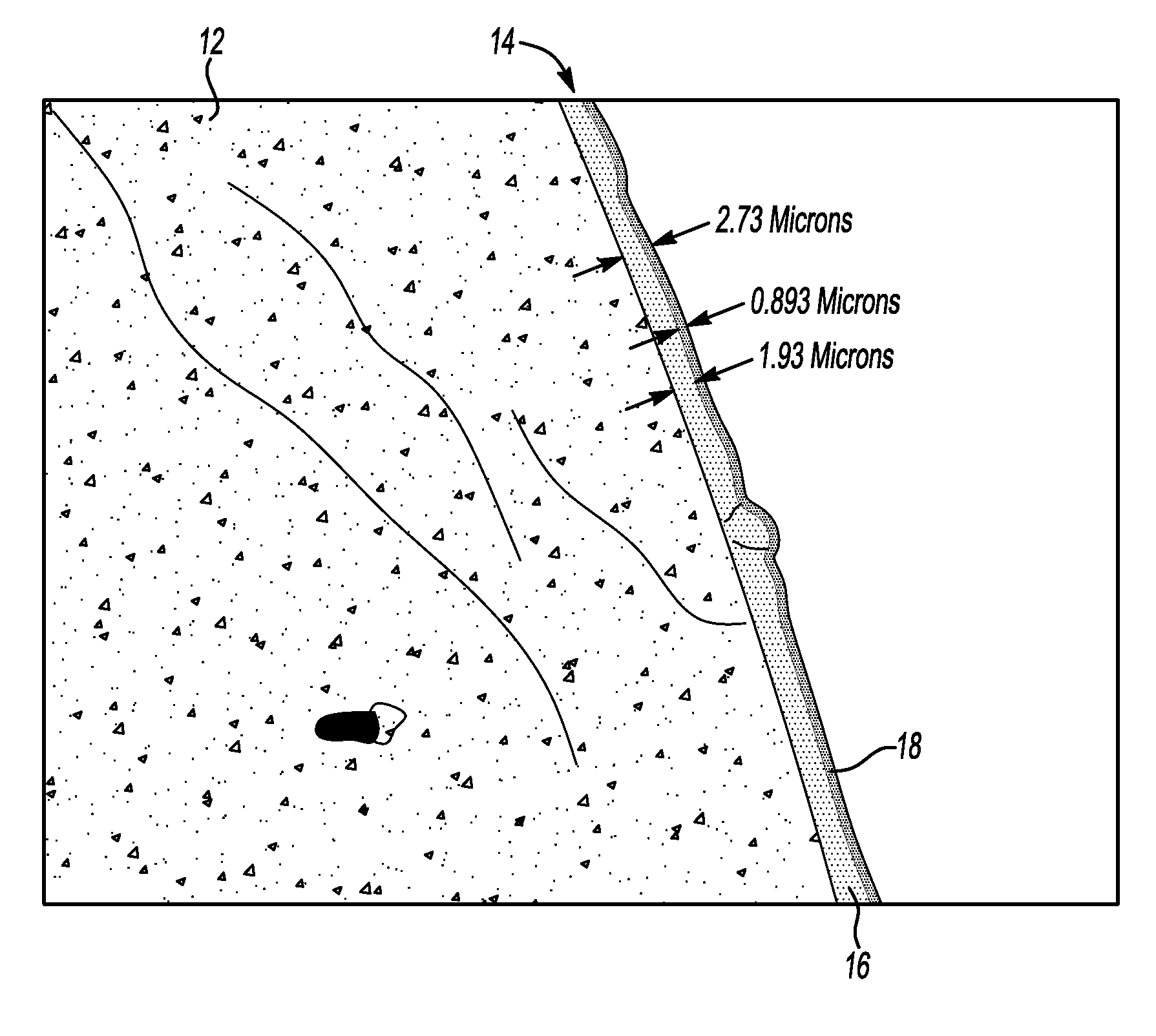
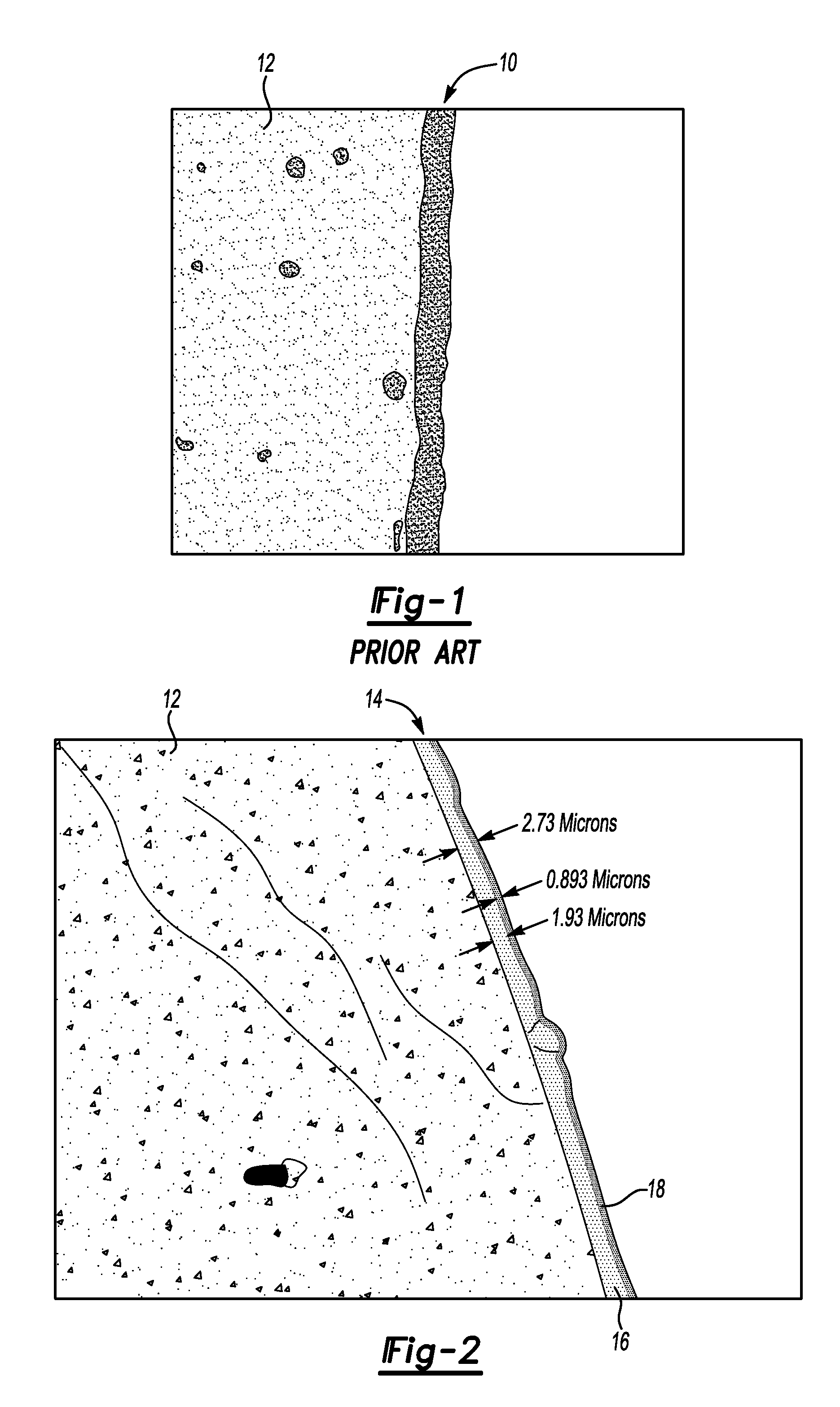
Image

Examples
example 1
[0040]In preparation for coating an M2 steel substrate with a coating of Example 1, the M2 steel substrate, two AlMgB14 targets, and two solid carbon targets are placed into a chamber of a CemeCon CC008® / 8 physical vapor deposition unit supplied with argon gas. Heating elements within the chamber are supplied with approximately 2,000 W to heat the M2 steel substrate to approximately 300° C. for 1 hour. During heating, pressure within the chamber is maintained at 8 mPa.
[0041]In preparation for etching the M2 steel substrate, the chamber is supplied with radio frequency power at 1,200 W for 1 hour. The M2 steel substrate is etched with argon gas having a flow rate of 75 ml / min. During etching, pressure within the chamber is maintained at 250 mPa.
[0042]To form a first layer of the coating on the M2 steel substrate, the two AlMgB14 targets are supplied with 1,500 W of power. During forming, argon gas is supplied to the chamber at a flow rate of 250 ml / min. The resulting first layer is f...
example 2
[0044]In preparation for coating an M2 steel substrate with a coating of Example 2, the M2 steel substrate and four AlMgB14 targets are placed into the chamber of the CemeCon CC008® / 8 physical vapor deposition unit supplied with separate streams of argon and acetylene gas. Heating elements within the chamber are supplied with approximately 2,000 W of power to heat the M2 steel substrate to approximately 300° C. for 1 hour. During heating, pressure within the chamber is maintained at 8 mPa.
[0045]In preparation for etching the M2 steel substrate, the chamber is supplied with radio frequency power at 1,200 W for 1 hour. The M2 steel substrate is etched with argon gas having a flow rate of 75 ml / min. During etching, pressure within the chamber is maintained at 250 mPa.
[0046]To form a first layer of the coating on the M2 steel substrate, the four AlMgB14 targets are supplied with 1,500 W of power. During forming, argon gas is supplied to the chamber at a flow rate of 250 ml / min. The resu...
example 3
[0048]In preparation for coating an M2 steel substrate with a coating of Example 3, the M2 steel substrate, two AlMgB14—TiB2 targets, and two solid carbon targets are placed into the chamber of the CemeCon CC008® / 8 physical vapor deposition unit supplied with argon gas. Heating elements within the chamber are supplied with approximately 2,000 W to heat the M2 steel substrate to approximately 300° C. for 1 hour. During heating, pressure within the chamber is maintained at 8 mPa.
[0049]In preparation for etching the M2 steel substrate, the chamber is supplied with radio frequency power at 1,200 W for 1 hour. The M2 steel substrate is etched with argon gas having a flow rate of 75 ml / min. During etching, pressure within the chamber is maintained at 250 mPa.
[0050]To form a first layer of the coating on the M2 steel substrate, the two AlMgB14—TiB2 targets are supplied with 1,500 W of power. During forming, argon gas is supplied to the chamber at a flow rate of 250 ml / min. The resulting fi...
PUM
| Property | Measurement | Unit |
|---|---|---|
| thickness | aaaaa | aaaaa |
| thickness | aaaaa | aaaaa |
| temperature | aaaaa | aaaaa |
Abstract
Description
Claims
Application Information