
Rotor shaft for a wind energy plant and wind energy plant

a technology of wind energy plants and shafts, which is applied in the direction of shafts, propellers, water-acting propulsive elements, etc., can solve the problems of increasing the dimensions of the transmission device, affecting the work of operators in the inner hub space, and inevitably stepping on the transmission device by entering persons, so as to facilitate installation and protect the transmission device. , good maintenance possibilities

Inactive Publication Date: 2010-02-04
NORDEX ENERGY
View PDF1 Cites 11 Cited by
  • Summary
  • Abstract
  • Description
  • Claims
  • Application Information

AI Technical Summary

Benefits of technology

The present invention relates to an improved design for a wind energy plant, particularly for a wind energy plant that uses a hollow rotor shaft. The invention includes a transmission device that is at least partly hollow and arranged in the rotor shaft. The transmission device features a first body and a second body that rotate with the rotor shaft. The first body is stationary and connected to the line pipe, while the second body rotates with the rotor shaft. The two bodies have an electric sliding contact, and a casing surrounds the transmission device to protect it from damage. The invention allows for easy installation and maintenance of the transmission device, and it simplifies the construction of the wind energy plant.

Problems solved by technology

In known wind energy plants, the transmission device is situated in the interior of the rotor hub, and through this it occupies significant space in the anyway limited inner space of the hub.
This makes the work of operators in the inner hub space difficult.
In particular, upon entrance into the rotor hub via additional rear entrance openings, an entering person inevitably steps on the transmission device.
It must be expected that this problem will be aggravated in the future, because future wind energy plants will require greater blade pitch adjustment powers and an increased expense for sensor technology, so that even the dimensions of the transmission devices will increase.
It comes along that with known rotor shafts and wind energy plants, the transmission device can be installed only at the location of the wind energy plant, because otherwise it would be damaged in the transportation of the plant or of the drive train, respectively, or in the building of the plant.
This leads to an increased expense for the installation.
Besides, the transmission device must be brought into the rotor hub for the installation on location, which means a risk of damage.
In addition, the utilisation of known constructions is difficult at rotor shafts formed hollow in a predominant part.
Furthermore, the known constructions are sumptuous with respect to their installation and do not always offer sufficient protection for the individual components of the transmission device.

Method used


Image

  • Rotor shaft for a wind energy plant and wind energy plant
  • Rotor shaft for a wind energy plant and wind energy plant

Examples


Embodiment Construction

[0026]While this invention may be embodied in many different forms, there are described in detail herein a specific preferred embodiment of the invention. This description is an exemplification of the principles of the invention and is not intended to limit the invention to the particular embodiment illustrated

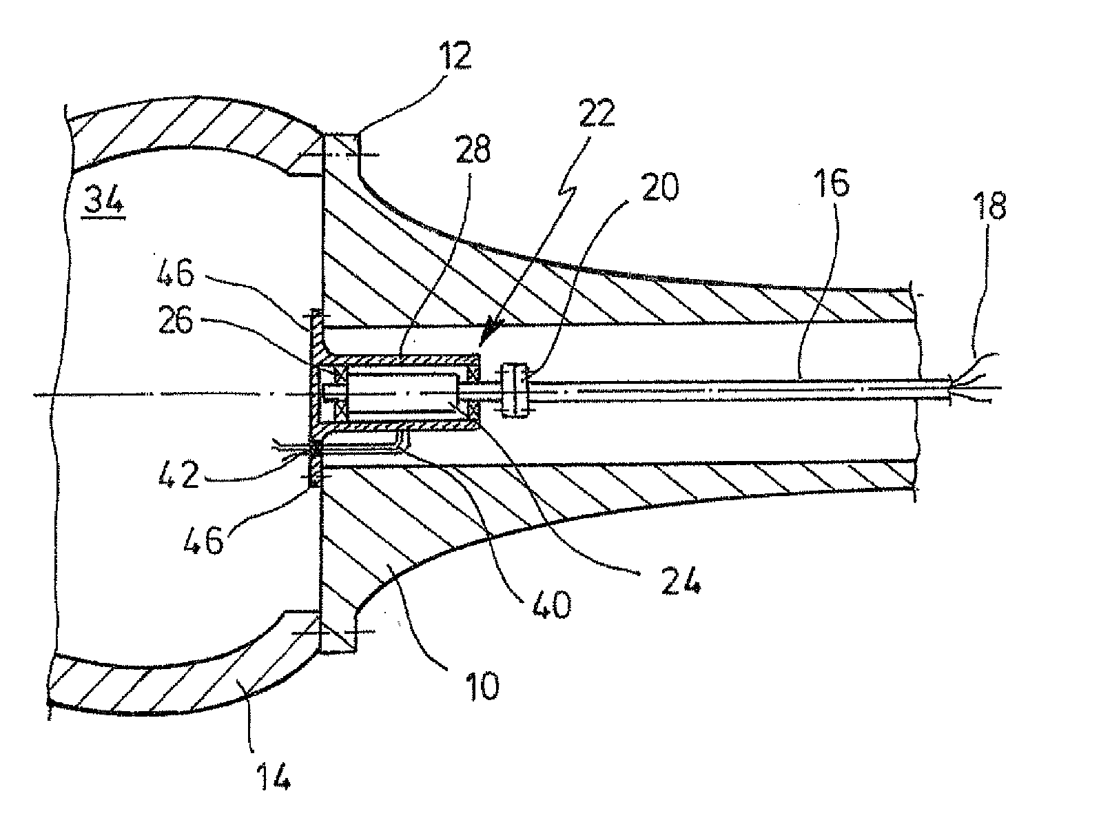
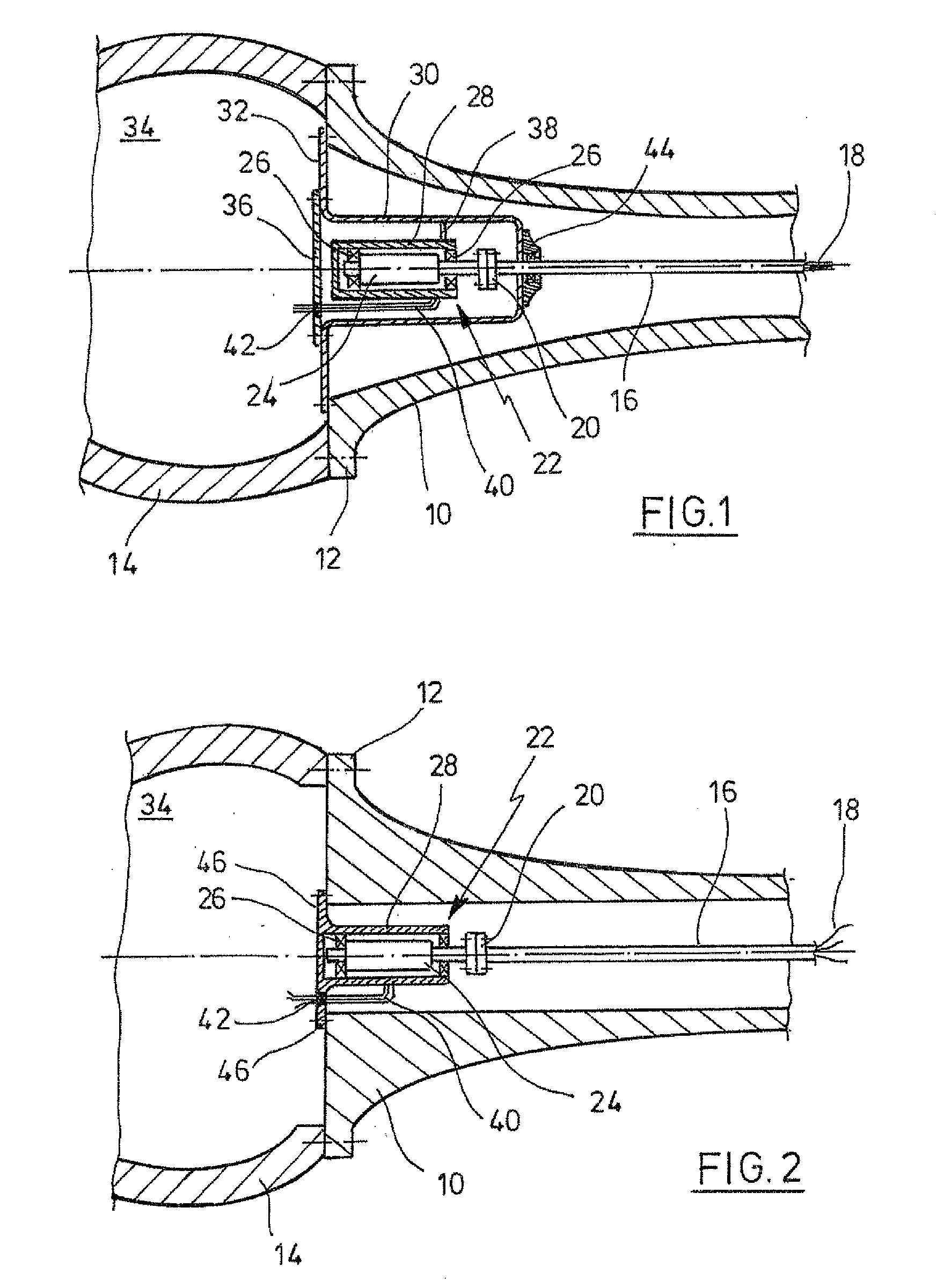
[0027]As far as not stated otherwise, equal reference signs designate equal objects in the figures. In FIG. 1 is shown a rotor shaft 10 of a wind energy plant not depicted in more detail, formed predominantly hollow according to the first aspect of the present invention. The rotor shaft 10 features a flange 12, by way of which it is fastened on a rotor hub 14 of the plant. In the interior of the rotor shaft 10 which rotates with the rotor hub 14 coaxially extends a stationary line pipe 16 (pitch pipe). The line pipe 16 guides electric lines 18 from the stationary nacelle (not depicted) of the wind energy plant in the direction of that end of the rotor shaft 10 which faces the ...


PUM


Abstract

The invention is related to a rotor shaft for a wind energy plant, wherein the rotor shaft is at least partially hollow, comprising a line pipe, extending in the interior of the rotating rotor shaft and being stationary and accommodating electric lines, a transmission device, arranged at least partially in the rotor shaft, for the electric connection between a stationary nacelle and a rotating rotor of the wind energy plant, wherein the transmission device features a first body, stationary and connected to the line pipe, and a second body rotating with the rotor shaft, and wherein there is an electric sliding contact between the first and the second body, a casing surrounding the transmission device and formed separately from the second body, which is connected to the rotor shaft and / or adapted to be connected to a rotor hub of the wind energy plant, and which rotates with the rotor shaft, and a torque transmitting connection between the casing and the second body of the transmission device.

Description

CROSS-REFERENCE TO RELATED APPLICATIONS[0001]Not applicable.STATEMENT REGARDING FEDERALLY SPONSORED RESEARCH[0002]Not applicable.BACKGROUND OF THE INVENTION[0003]The present invention is related to a rotor shaft for a wind energy plant, as well as to a wind energy plant. Wind energy plants with an electric blade angle control (pitch control) are often equipped with a slip ring system, which transmits electric energy and signals as a transmission device from the stationary electric system of the nacelle of the plant into the pitch system in the rotor hub assembly group that rotates with the rotor of the plant. For this purpose, known rotor shafts have a core bore, in which a stationary line pipe (also pitch pipe) extends. The line pipe has the objective to accommodate and protect the electric lines which are to be guided from the stationary nacelle into the rotating rotor hub. Usually, it begins behind the gearbox, where it is also mounted, and guides the lines from there up to the i...

Claims


Application Information

Patent Timeline
Patent Type & Authority Applications(United States)
IPC IPC(8): F16C3/00
CPCF03D11/00F03D11/0066F05B2260/40F05B2240/61Y02E10/721Y02E10/722F05B2260/76F03D80/00F03D80/70F03D80/85Y02E10/72
Inventor GOPFERT, ULFKAISER, UWE
Owner NORDEX ENERGY
Learn More