Superconducting coil and superconductor used for the same

a superconducting coil and coil technology, applied in the field of superconducting coils, can solve the problems of high wire cost and difficulty in making a long length of uniform wire, and achieve the effect of high magnetic field

Active Publication Date: 2010-02-04
SUMITOMO ELECTRIC IND LTD
View PDF2 Cites 6 Cited by
  • Summary
  • Abstract
  • Description
  • Claims
  • Application Information

AI Technical Summary

Benefits of technology

[0015]According to the present invention, a low-cost superconducting coil in which a high magnetic field can be generated at comparatively high temperature can be realized.

Problems solved by technology

However, the tape-shaped RE123 superconducting wire, the manufacturing process of which is complicated and delicate, is difficult to make a long length of uniform wire that can be formed into a coil with a single length thereof.
Also, the wire cost is high because of the low yield.

Method used


Image

  • Superconducting coil and superconductor used for the same
  • Superconducting coil and superconductor used for the same
  • Superconducting coil and superconductor used for the same

Examples


embodiment

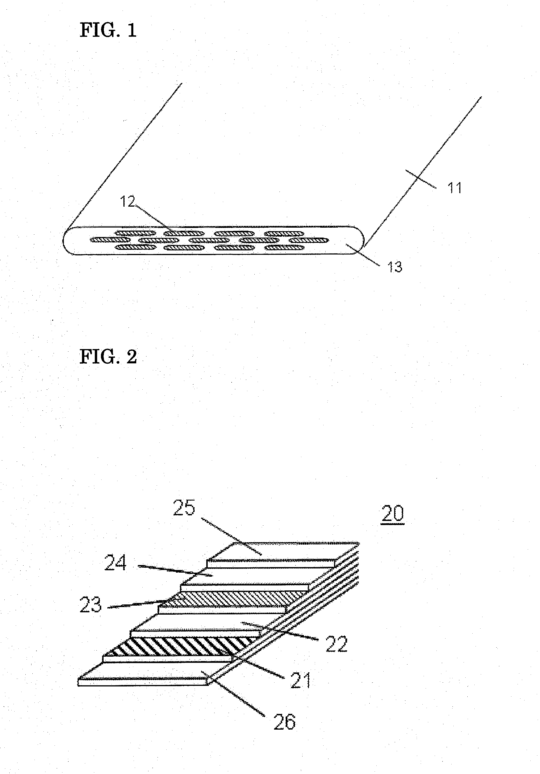
[0038]FIG. 1 is a partial sectional perspective view schematically showing a structure of the tape-shaped (Bi,Pb)2223 superconducting wire. In reference to FIG. 1, the tape-shaped (Bi,Pb)2223 superconducting wire having a number of filaments will be explained. A tape-shaped (Bi,Pb)2223 superconducting wire 11 has a plurality of (Bi,Pb)2223 superconductor filaments 12 extending in a longitudinal direction and a sheath portion 13 covering them. The material of the sheath portion 13 is composed of, for example, metal such as silver and silver-based alloy.

[0039]FIG. 2 is a partial sectional perspective view schematically showing a structure of the tape-shaped RE123 superconducting wire. In reference to FIG. 2, a typical tape-shaped RE123 superconducting wire will be explained. A tape-shaped RE123 superconducting wire 20 comprises a textured metal substrate 21 as the substrate, a buffer layer 22 formed on the textured metal substrate 21, a superconducting thin-film layer 23 formed on the...

example

[0068]Sixty pieces of the tape-shaped (Bi,Pb)2223 superconducting wire, which had a width of 4.3±0.1 mm, a thickness of 0.24±0.01 mm, and a length of 180 m, and sixty pieces of the tape-shaped RE123 superconducting wire, which had a width of 4.30±0.05 mm, a thickness of 0.1±0.002 mm, and a length of 40 m, were prepared. These wires had a critical-current value of 190 A to 200 A at the liquid-nitrogen temperature. Sixty pieces of series conductors were made by soldering one kind of theses wires with the other kind of theses wires at one end of each piece thereof.

[0069]These series conductors were laminated with a stainless steel tape having a thickness of 0.1 mm and a polyimide tape having a thickness of about 15 μm for an insulating layer between the constituent superconducting layers. The so-constructed conductors were wound around a bobbin from the side of the tape-shaped RE123 superconducting wire such that the tape-shaped RE123 superconducting wire was arranged in the internal c...


PUM

PropertyMeasurementUnit
temperatureaaaaaaaaaa
magnetic fieldaaaaaaaaaa

Abstract

A low-cost superconducting coil which can generate a high magnetic field at comparatively high temperature is provided. The superconducting coil is formed in a pancake shape by winding a superconducting conductor that is made by electrically connecting a tape-shaped (Bi,Pb)2223 superconducting wire and a tape-shaped RE123 superconducting wire in series such that the tape-shaped (Bi,Pb)2223 superconducting wire is arranged in the outer circumferential part and the tape-shaped RE123 superconducting wire is arranged in the internal circumferential part.

Description

TECHNICAL FIELD[0001]The present invention relates to a superconducting coil, and more particularly to a structure of superconducting coil that is capable of generating a high magnetic field at high operation temperature.BACKGROUND ART[0002]As for superconducting wires using oxide superconducting materials, there are the following two kinds that are under intensive development at present: one is a tape-shaped silver sheathed superconducting wire made by a powder-in-tube method and having (Bi,Pb)2Sr2Ca2Cu3O10δ phase as a main component (δ is a number on the order of 0.1: hereinafter, referred to as (Bi,Pb)2223). (For example, refer to Non-patent Document 1.) The other one is a tape-shaped thin-film superconducting wire in which a superconducting layer is formed on a metallic substrate by a vapor-phase method or a liquid phase method. The superconducting material of the thin-film superconducting wire is an oxide superconducting material represented by the chemical formula of RE1Ba2Cu3...

Claims


Application Information

Patent Timeline
Patent Type & Authority Applications(United States)
IPC IPC(8): H01F6/06H01B12/02
CPCH01F6/06Y10S505/879Y10S505/705Y10S505/844H01B12/02
Inventor KOBAYASHI, SHINICHI
Owner SUMITOMO ELECTRIC IND LTD
Why Eureka
Try Eureka