System and method for harnessing wind power at variable altitudes

a technology of wind power and variable altitude, applied in the direction of electric generator control, machines/engines, mechanical equipment, etc., can solve the problems of inconvenient operation, inability to sustain and effective power production in the near-ground environment, and inability to meet the needs of sustainable and effective power production, etc., to achieve maximum tensile strength, minimize energy loss in the system, and high specific strength

Inactive Publication Date: 2010-02-11
CMNA POWER
View PDF3 Cites 21 Cited by
  • Summary
  • Abstract
  • Description
  • Claims
  • Application Information

AI Technical Summary

Benefits of technology

[0012]An exemplary embodiment may have a minimum plurality of lines with a strength to density ratio of at least 250 kN*m / kg, which may be constructed of carbon nanotubes, carbon fiber, Ultra High Molecular Weight Polyethylene (UHMWPE) synthetic rope, Cuben Fiber, Plasma®, PBO, Kevlar®, Aramid®, M5®, Zylon®, braid optimized for bending (BOB), a hybrid rope, which all have been shown to have high specific strengths. The lines are constructed with minimal mass to permit lift of said wind capturing structure at low altitudes, and are constructed with maximum tensile strength to prevent failure in high wind environments. In a preferred embodiment, the lines that control the wind capturing structure could not slip on the spool during normal operation.
[0013]The winding structure may be a spool, spindle, reel, coil, or any structure capable of rotating about an axis. The preferred embodiment could also minimize energy losses in the system for maximum efficiency.
[0014]A versatile wind capturing structure could include a kite operable in variable conditions for efficient and consistent production of the force, lines with a minimum tensile strength to density ratio 250 kN*m / kg for linear motion generation, a velocity controller for controlling the rotational motion and the linear motion, and drag coefficient controller for adapting the kite's drag coefficient and / or cross-sectional area (also referred to as “reference” area) for optimizing power output and / or input. The versatile wind capturing structure may be adaptable by drag coefficient and velocity controller. Control via the lines allows for the entire system to be efficient and consistently generate force for power production. An exemplary embodiment of velocity control may be accomplished by altering a load upon a generator. Similarly the velocity could be controlled by altering the drag force of the wind capturing structure. Altering the drag force could be accomplished by folding, deforming, re-orienting, or some other means of reducing drag on the wind capturing structure.
[0015]The power producing cycle of a system generating electrical power from wind has the steps of unwinding the winding structure to create linear motion for producing rotational motion, coupling the winding structure to a generator for power production, slowing down the linear motion, reducing the drag for retrieval, altering the winding structure to operate in reverse for retrieving the system, and starting the cycle again. The retrieval energy used should be kept to a minimum to maximize the efficiency of the system.

Problems solved by technology

This environment has variable wind conditions, as well as inconsistent direction and intensity.
The environment near the ground is not financially and operationally practical for sustainable and effective power production.
A basic reason a kite system may be operationally impractical in an environment away from the ground is that the materials used to manufacture the kites have developed slowly.
Kite system safety measures are another area where development has been slow.
Broken lines and lost kites are not only expensive, but may be dangerous.
Inherently each disclosure is also very complicated and not functional in producing efficient power.

Method used


Image

  • System and method for harnessing wind power at variable altitudes
  • System and method for harnessing wind power at variable altitudes
  • System and method for harnessing wind power at variable altitudes

Examples


Embodiment Construction

[0022]While making and using various embodiments of the present disclosure are discussed in detail below, it should be appreciated that a preferred embodiment provides many applicable inventive concepts, which may be embodied in a wide variety of specific contexts. The specific embodiments discussed herein are merely illustrative of specific ways to make and use the present disclosure and do not delimit the scope of the present disclosure.

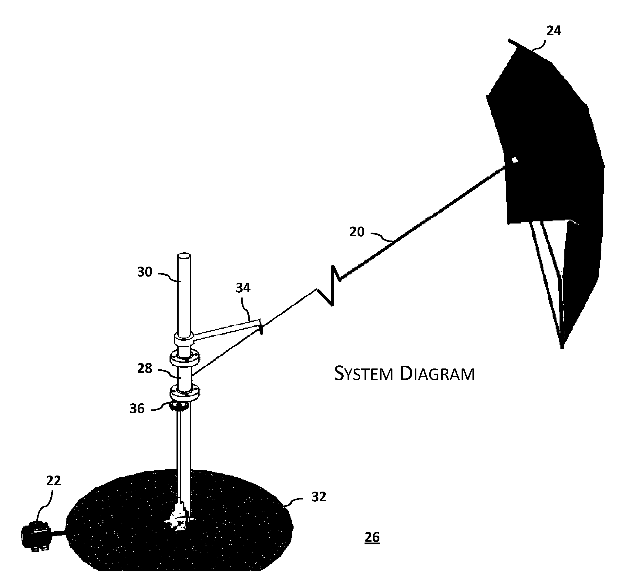
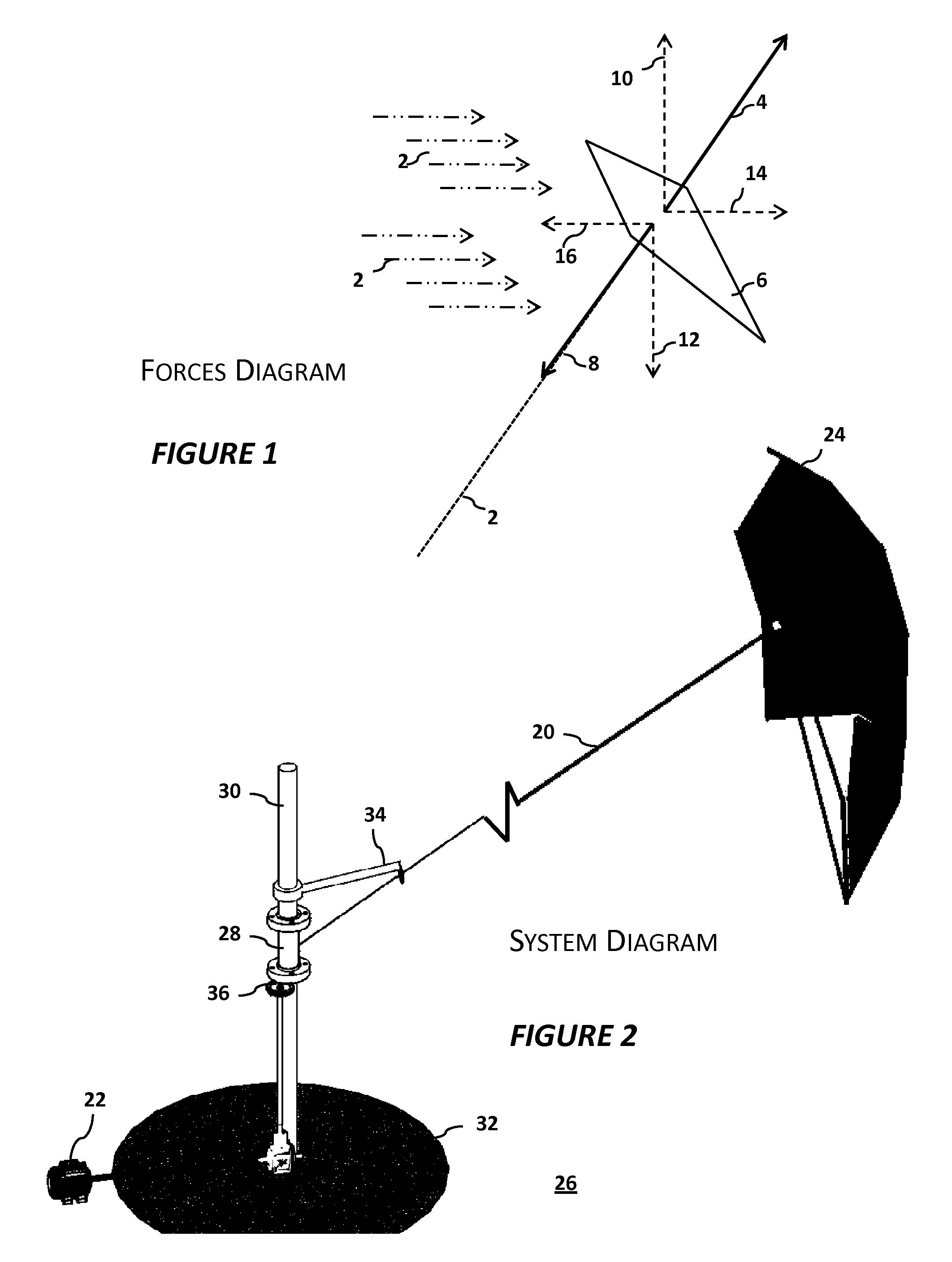
[0023]The present disclosure involves using a wind capturing structure (a kite) to power a system that produces electrical energy in the most simple and efficient way. FIG. 1 shows that the system relies on wind 2 causing wind force 4 on kite 6. Kite 6 remains in flight by flying at an angle to the anchor (in recreational kites, the anchor may be the user); wind force 4 occurs in the opposite direction of the anchoring line 8. To be effective, wind force 4 must create enough force that vertical wind force component 10, referred to as “lift” is equa...


PUM


Abstract

A system for harnessing power from wind using a wind capturing structure. An axis of rotation could be central to the system, and the lines could rotate around this axis. Features for the wind capturing structure include effective downwind power generation using a durable, lightweight, inexpensive structure that may be safe in the event of a crash, and easily modified to reduce drag for retraction. The capturing structure creates lift in a low altitude environment, capable of operating in high wind conditions. The lines include minimal mass to permit lift at low altitudes, and are constructed with maximum tensile strength to prevent failure in high winds. A versatile wind capturing structure could include a kite operable in variable conditions for efficient and consistent production of force. The power producing cycle of a system capturing power from wind should maximize the efficiency of the system.

Description

TECHNICAL FIELD OF THE INVENTION[0001]The present invention relates to devices that produce useful power from wind energy—more specifically to devices that extract power using tethered kites and a generator.DESCRIPTION OF THE RELATED ART[0002]The kite is a very old technology, and has been used for centuries as entertainment and as a common toy. More recently, kites have been used to help tow many different types of vehicles, from skateboards and surfboards to boats.[0003]Typically kites are used close to the ground, and are controlled by multiple lines operated by one person. This environment has variable wind conditions, as well as inconsistent direction and intensity. The environment near the ground is not financially and operationally practical for sustainable and effective power production.[0004]A basic reason a kite system may be operationally impractical in an environment away from the ground is that the materials used to manufacture the kites have developed slowly. Combining...

Claims


Application Information

Patent Timeline
Patent Type & Authority Applications(United States)
IPC IPC(8): F03D5/00
CPCF03D5/00F03D11/04Y02E10/728Y02E10/70F05B2240/921F03D13/20Y02E10/72F03D9/25
Inventor VARRICHIO, CRAIGLANDRY, MARKVARRICHIO, ANTHONY
Owner CMNA POWER
Why Eureka
Try Eureka