Devices for removing particles from a gas comprising an electrostatic precipitator

a technology of electrostatic precipitator and gas, which is applied in the direction of electrostatic separation, chemistry apparatus and processes, human health protection, etc., can solve the problem of not uniform current density at these different portions of the receptor electrode, and achieve the effect of enhancing the uniformity of current density

Inactive Publication Date: 2010-02-18
C C & L COMPANY
View PDF24 Cites 21 Cited by
  • Summary
  • Abstract
  • Description
  • Claims
  • Application Information

AI Technical Summary

Benefits of technology

[0005]Embodiments of the present invention enhance the uniformity of the current density between an emitter and one or more receptor electrodes having flat surfaces or ...

Problems solved by technology

In other words, the current density will not be unif...

Method used


Image

  • Devices for removing particles from a gas comprising an electrostatic precipitator
  • Devices for removing particles from a gas comprising an electrostatic precipitator
  • Devices for removing particles from a gas comprising an electrostatic precipitator

Examples


example

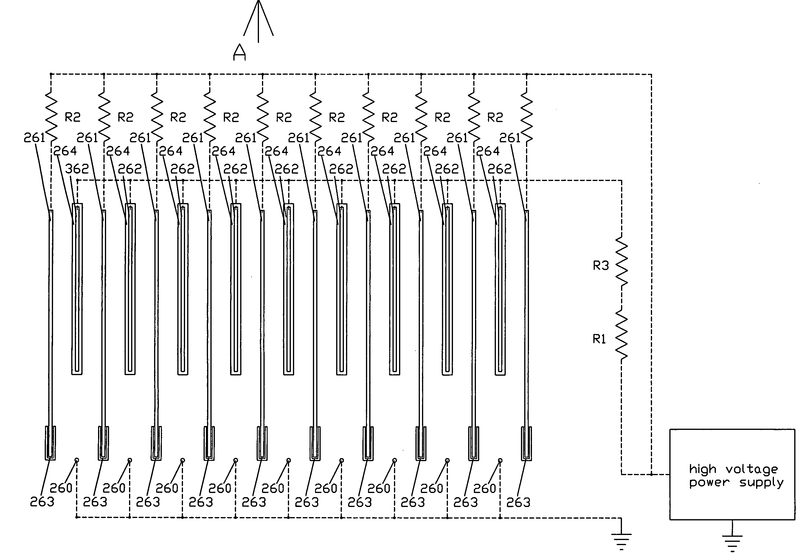
[0120]A comparison test was performed using air cleaners arranged in the configurations shown in FIG. 25 and FIG. 26. In the FIG. 25 configuration, the receptor / collector electrode plates 251 were 450 mm long, 100 mm wide and 0.5 mm thick aluminum sheet. These receptor / collector electrodes were spaced 14 mm apart in a parallel manner. The emitter wires 250 were a commercially available 0.12 mm diameter tungsten wire. Ten receptor / collector plates 251, nine emitter wires and nine driver electrodes 252 insulated with insulator 254 were arranged as shown in FIG. 25. A potential difference of about 5 Kv was applied between the emitter wire and the receptor / collector plates to produce a corona current of about 350 microampere without arcing. The CADR (clean air delivery rate) for dust as defined in ANSI / AHAM AC-1-2006 and the ozone concentration according to UL Ozone Standard 867 were measured. This arrangement had a CADR for dust of around 160 and generated 7 parts per billion ozone.

[01...


PUM


Abstract

Air or gas cleaners enhance the uniformity of the current density between an emitter and one or more receptor electrodes by positioning one or more insulators or effective resistors between the emitter and the receptor electrode. Insulators and/or effective resistors are used to shield select portions, e.g. the edges of plate-type receptor electrodes, from ionization current flowing between an emitter and unshielded portions. This allows more compact structures without ionization current concentrations at the shielded regions, and results in lower ozone generation for a given particle collection efficiency.

Description

[0001]The present invention relates to devices for removing particles from gases comprising an electrostatic precipitator, and is particularly suited for air cleaners.BACKGROUND[0002]Various types of electrostatic air cleaners are already known in the art. The arrangement of some basic elements of two types of electrostatic air cleaners known in the prior art are shown in FIGS. 1 and 2. The device shown in FIG. 1 uses a wire as the emitter and plates as integrated receptor / collector structure. The device shown in FIGS. 2A and 2B uses a pin point type emitter and a tube as the integrated receptor / collector structure. All of the elements illustrated in FIGS. 1 and 2 are made of electrical conductors. As a high enough electrical potential difference is applied between the emitters and the receptor / collector structures, the air gap between them becomes partially conductive and an electrical current flows across the gap. This region is known as a corona and the current created is called ...

Claims


Application Information

Patent Timeline
IPC IPC(8): B03C3/12
CPCB03C3/08B03C3/12B03C3/84B03C3/60B03C3/47Y02A50/2351
Inventor CHAN, SIK LEUNG
Owner C C & L COMPANY
Why Eureka
Try Eureka