
Single-inductor buck-boost converter with positive and negative outputs

a single-inductor, buck-boost technology, applied in the direction of electric variable regulation, process and machine control, instruments, etc., can solve the problems of prior art four-switch power converters subject to constraints, power converters that do not provide buck-boost capability or bipolar voltage output capabilities, etc., to achieve the effect of reducing the ripple of output voltage and cos

Inactive Publication Date: 2010-02-18
ASAHI KASEI TOKO POWER DEVICE
View PDF13 Cites 108 Cited by
  • Summary
  • Abstract
  • Description
  • Claims
  • Application Information

AI Technical Summary

Benefits of technology

[0006]In the design of portable electronic products, such as mobile communications gear, there is a need for low-cost, efficient, and physically compact power conversion circuits. For example, the required positive and negative voltages powering a cell phone's active-matrix organic LED display driver are sometimes generated using a two-inductor switch-mode power supply. Since inductors tend to be relatively large and represent additional cost, a single-inductor approach which produces bipolar outputs would be attractive. In accordance with the present invention, a single-inductor switch-mode converter produces bipolar output voltages and is capable of buck-boost operation to either step up or step down the input source voltage.
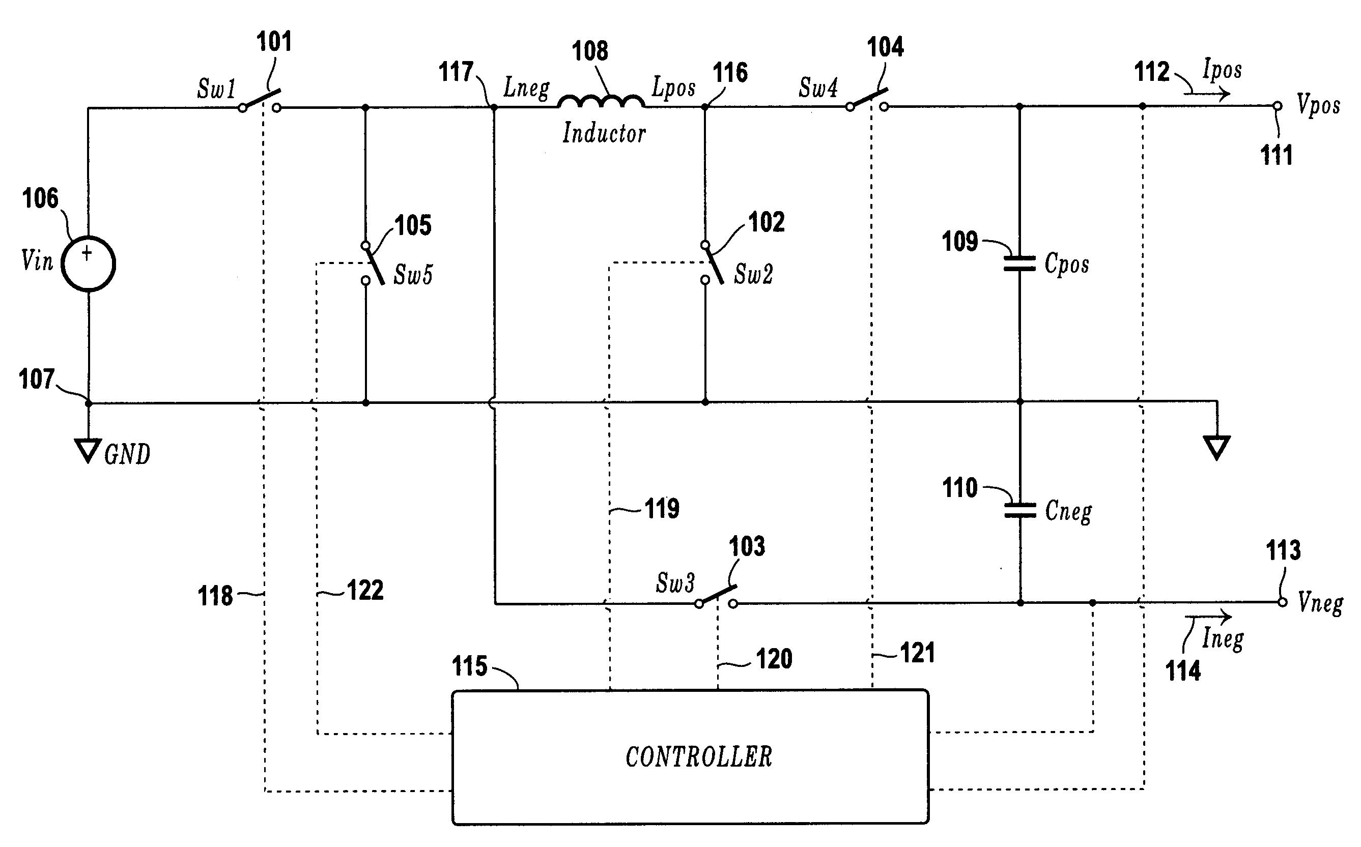
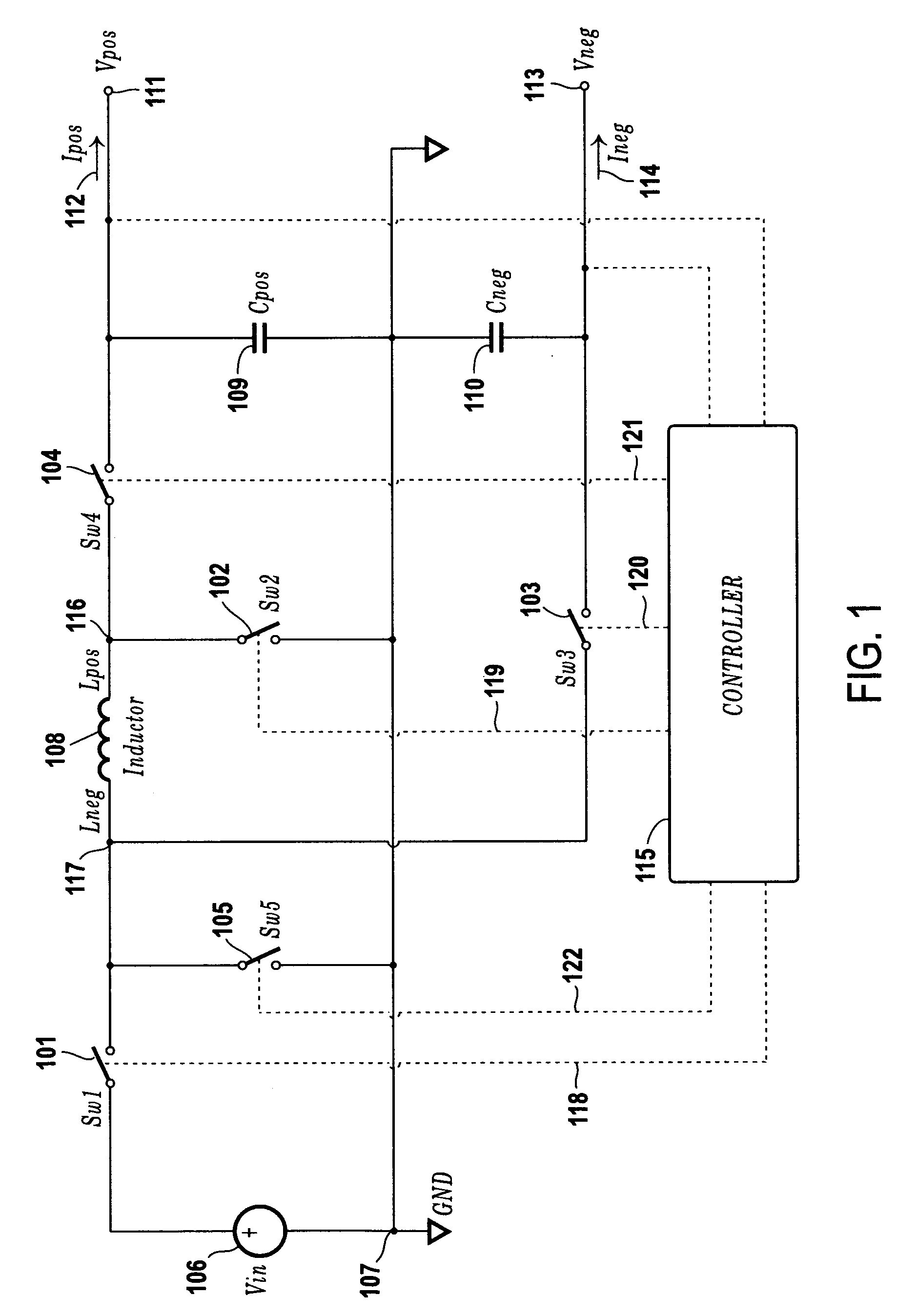
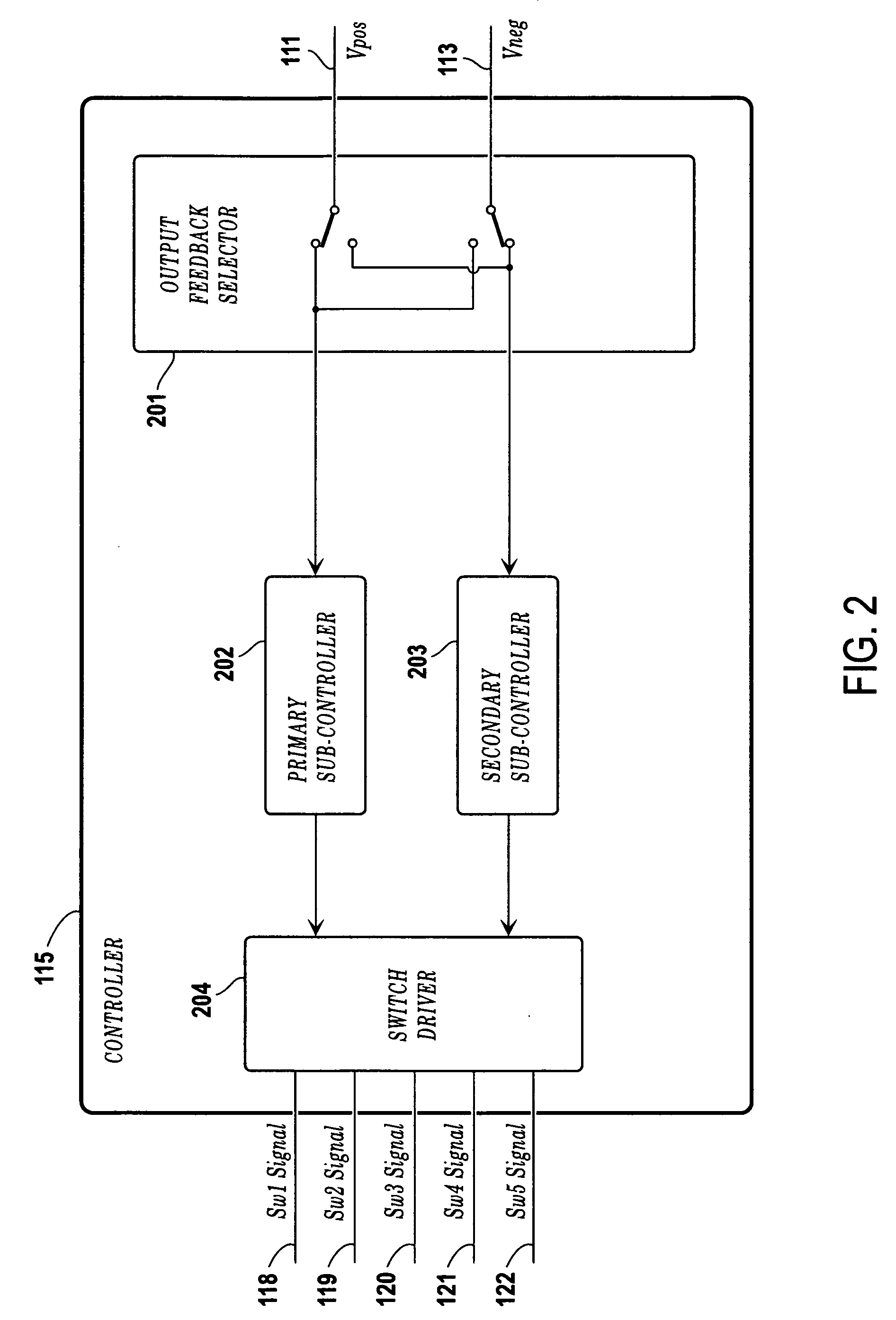
[0007]The power converter of the present invention employs a single inductor and produces two output voltages of opposite polarity with respect to ground from a single input supply voltage. Its buck-boost capability permits the output voltages to be either higher or lower than the input supply voltage source and to be independently adjustable by means of feedback component selection. These important features are accomplished through the use of a five-switch bridge. Two of the switches are capable of steering inductor current to ground which, under direction from a controller, allows inductor current to be diverted away from either output as needed to maintain proper output voltage regulation. In the preferred embodiment, the inductor current can be delivered to both outputs during a single switching cycle. The result is a lower output voltage ripple compared to prior art power converters which steer pulses of inductor current to an output terminal on alternating switch cycles.

Problems solved by technology

However, unlike the preset invention, the circuit topologies and switch sequence operations described in the prior art do not provide buck-boost capability with the generation of bipolar output voltages.
However, like other known power converters, this power converter does not provide the buck-boost or bipolar voltage output capabilities of the present invention.
By contrast, the prior art four-switch power converters are subject to those constraints.

Method used


Image

  • Single-inductor buck-boost converter with positive and negative outputs
  • Single-inductor buck-boost converter with positive and negative outputs
  • Single-inductor buck-boost converter with positive and negative outputs

Examples


Embodiment Construction

[0014]Referring now to FIG. 1, there is shown a buck-boost SI-MO power converter circuit in accordance with the present invention that employs a single inductor and a five-switch bridge. The circuit utilizes a single source of supply voltage 106 to produce positive and negative output voltages at output terminals 111, 113, with respect to circuit ground terminal 107. An input switch 101 connects the supply voltage 106 to a first terminal 117 of an inductor 108. A switch 105 is connected between terminal 117 of inductor 108 and ground terminal 107. A switch 103 is connected between terminal 117 of inductor 108 and a negative output terminal 113. A switch 102 is connected between a second terminal 116 of inductor 108 and ground terminal 107. A switch 104 is connected between terminal 116 of inductor 108 and a positive output terminal 111. Switches 103, 104 may be replaced by conventional diode devices. A first capacitor 109 is connected between positive output terminal 111 and ground ...


PUM


Abstract

A single-inductor power converter with buck-boost capability provides regulated bipolar output voltage to a positive and a negative load. A five-switch bridge topology allows a controller to direct the inductor current to the appropriate outputs or circuit ground as needed to maintain regulation. The controller also adjusts the inductor current level for proper output voltage regulation. The five-switch bridge topology makes possible a wide range of ratios between the positive and negative output currents of the converter.

Description

BACKGROUND AND SUMMARY OF THE INVENTION[0001]This invention relates to single-inductor switch-mode power conversion circuit topologies which function to produce bipolar outputs of positive and negative polarity. This class of power converters is sometimes referred to as SI-MO (Single-Inductor, Multiple-Output).[0002]Several types of power converters are known in the prior art, the most common type being the Single-Inductor, Multiple-Input, Multiple-Output (SI-MIMO) power converter. U.S. Pat. No. 7,256,568 describes a step-down or buck converter in which the input-side and output-side switches are used for the dual purposes of time-multiplexing various input sources and output loads and performance of the buck mode of operation. Additionally, U.S. Pat. Nos. 6,222,352; 7,061,214; and 7,224,085 are directed to various SI-MO buck converters. However, unlike the preset invention, the circuit topologies and switch sequence operations described in the prior art do not provide buck-boost ca...

Claims


Application Information

Patent Timeline
IPC IPC(8): G05F1/10
CPCH02M2001/009H02M3/1582H02M1/009
Inventor SCHOENBAUER, STEVEMARTIN-LOPEZ, FERNANDO R.
Owner ASAHI KASEI TOKO POWER DEVICE
Learn More