Tunable multi-zone gas injection system

a gas injection system and multi-zone technology, applied in the direction of mechanical equipment, radial flow pumps, machines/engines, etc., can solve the problems of inability to achieve the effect of reducing the number of injections

Active Publication Date: 2010-02-18
LAM RES CORP
View PDF59 Cites 35 Cited by
  • Summary
  • Abstract
  • Description
  • Claims
  • Application Information

AI Technical Summary

Benefits of technology

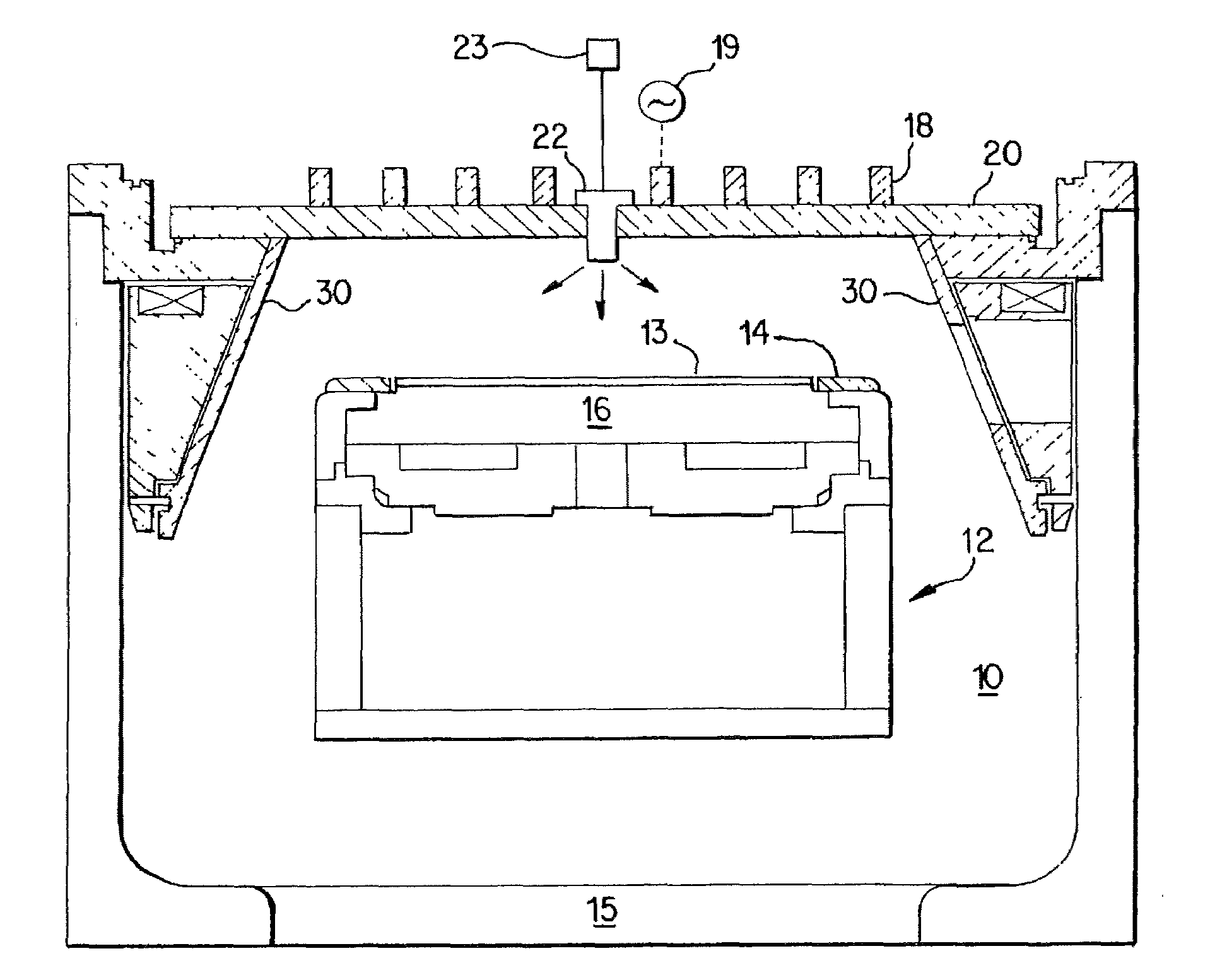
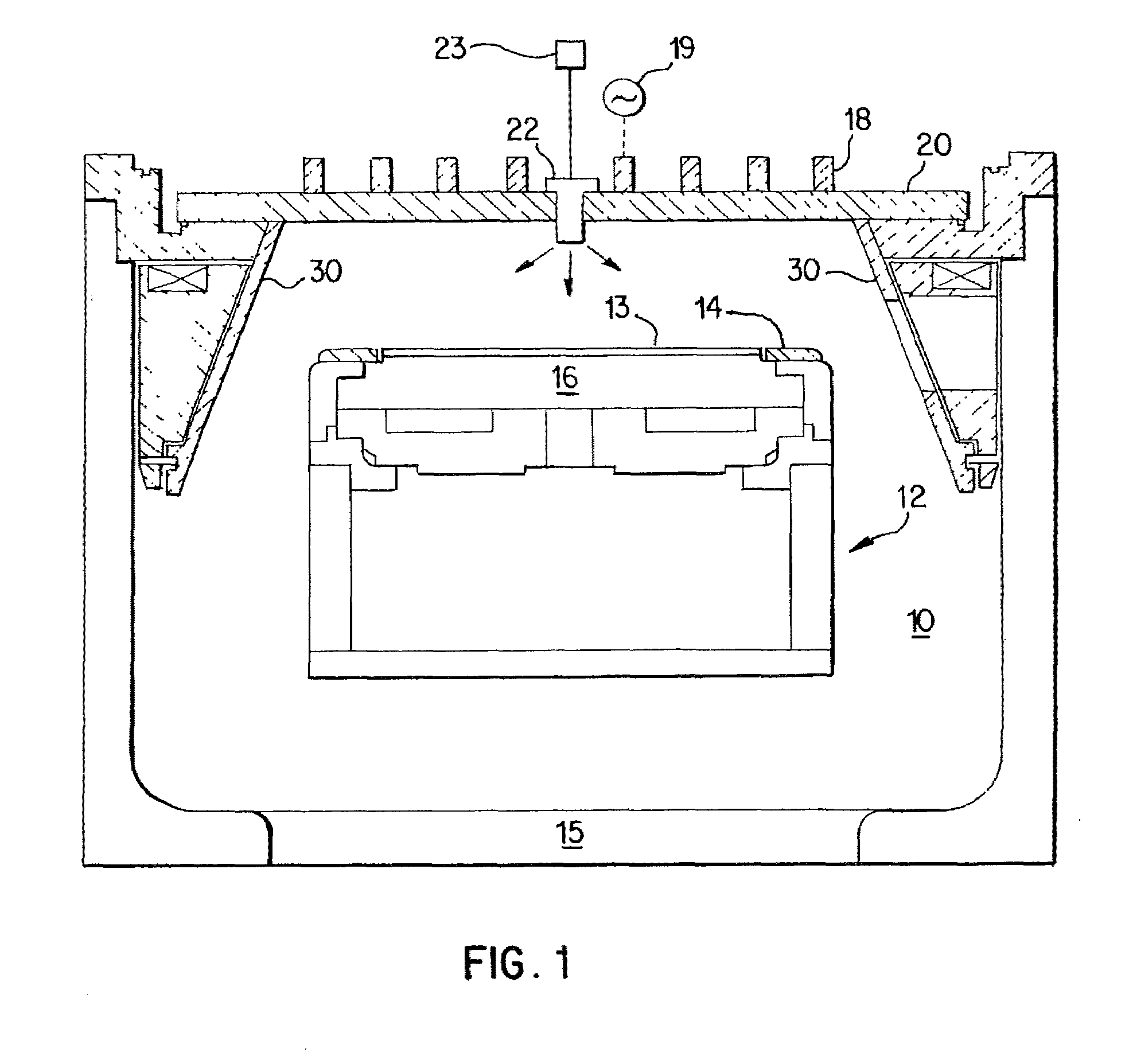
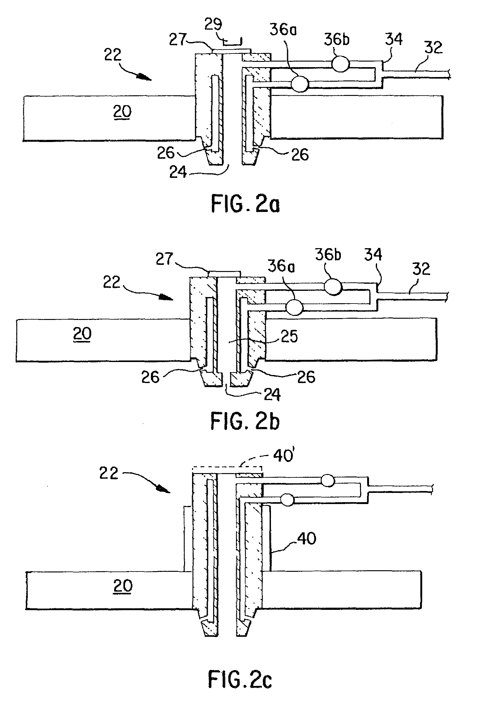
[0017]The RF energy source can comprise an RF antenna and the gas injector can inject the process gas toward a primary plasma generation zone in the chamber. The gas outlets can be located in an axial end surface of the gas injector thus forming several gas outlet zones. For instance, the gas outlets can include a center gas outlet (on-axis zone) extending in an axial direction perpendicular to the exposed surface of the substrate and a plurality of angled gas outlets (off axis zones) extending at an acute angle to the axial direction. The injector outlets are positioned to improved uniformity of reactive species over the substrate. A single gas supply is split to feed each of the injection zones.
[0018]Gas injection can be partitioned between o

Problems solved by technology

This can lead to an undesirable loss in etch and deposition uniformity.
These conduit arrangements can cause process drift problems as a result of heating of the ends of the conduits.
Injectors with the orifices located at the distal ends of the injector tubes may be prone to clogging after processing a relatively small batch of substrates, e.g., less than 100.
This injector orifice clogging is detrimental as it can lead to nonuniform distribution of reactants, nonuniform film deposition or etching of the substrate, shifts in the overall deposition or etch rate, as well as economic inefficiency vis-à-vis tool downtime due to required maintenance.
This second design can improve reactive neutral densities over the substrate but requires the presence of a conducting g

Method used


Image

  • Tunable multi-zone gas injection system
  • Tunable multi-zone gas injection system
  • Tunable multi-zone gas injection system

Examples


example 1

[0055]Polysilicon etch depth statistics (mean, standard deviation, and range) were measured as a function of on-axis:off-axis gas flow ratio. FIGS. 4a-c show etch profiles for a gate etch process wherein FIG. 4a shows the effect of higher on-axis gas injection and FIG. 4c shows the effect of higher off-axis injection. Predominately on-axis flow conditions produced an etch depth of 212.9±4.7 nm (±2.2%) and a range of 18.3 nm (±1.4%) (see polysilicon etch results in FIG. 4a). Predominately off-axis flow conditions produced an etch depth of 212.6±5.3 nm (±2.5%) and a range of 22.3 nm (±1.7%) (see polysilicon etch results in FIG. 4c). A mixed gas flow condition, in contrast, produced a dramatic improvement in etch uniformity (see polysilicon etch results in FIG. 4b). Under the mixed flow conditions, the mean etch depth was 213.5±2.3 nm (±1.1%), with a range of only 7.7 nm (±0.6%). The polysilicon etch used a Cl2 / HBr / O2 flow mixture at a total flow of 420 scm and a chamber pressure of 10...

example 2

[0056]Silicon etch depth statistics (mean, standard deviation, and range) were measured as a function of on-axis:off-axis gas flow ratio. FIGS. 5a-c show etch rate profiles for a gate etch process wherein FIG. 5a shows the effect of higher on-axis gas injection and FIG. 5c shows the effect of higher off-axis injection. Predominately on-axis flow conditions produced an etch depth of 1299 A±27 A (±2.1%) and a range of 74 A (±1.0%) (see polysilicon etch results in FIG. 5a). A mixed gas flow condition produced an etch depth of 1295 A±23 A (±1.8%) and a range of 76 A (±1.0%) (see polysilicon etch results in FIG. 5b). Predominately off-axis flow conditions produced a dramatic improvement in etch uniformity (see polysilicon etch results in FIG. 5c). Under the off-axis flow conditions, the mean etch depth was 1272 A±14 A (±1.1%), with a range of 41 A (±0.53%). The silicon etch used an HBr / O2 flow mixture at a chamber pressure of 40 mT and a bottom electrode temperature of 60°. The RF antenn...

example 3

[0057]FIGS. 6a-b show polysilicon gate critical dimension (CD) variation as a difference between pre- and post-etch for two different gas flow ratios. Increased on-axis flow is shown in FIG. 6a in comparison with increased off-axis flow shown in FIG. 6b. The use of tunable injection results in better CD uniformity. In particular, the results shown in FIG. 6a provided a mean CD variation of −3.9 nm, standard deviation of 2.1 nm and range of 7.5 nm whereas the results shown in FIG. 6b provided a CD variation of −3.4 nm, standard deviation of 1.6 nm and range of 5.9 nm.


PUM

PropertyMeasurementUnit
Timeaaaaaaaaaa
Angleaaaaaaaaaa
Angleaaaaaaaaaa

Abstract

A tunable multi-zone injection system for a plasma processing system for plasma processing of substrates such as semiconductor wafers. The system includes a plasma processing chamber, a substrate support for supporting a substrate within the processing chamber, a dielectric member having an interior surface facing the substrate support, the dielectric member forming a wall of the processing chamber, a gas injector fixed to part of or removably mounted in an opening in the dielectric window, the gas injector including a plurality of gas outlets supplying process gas at adjustable flow rates to multiple zones of the chamber, and an RF energy source such as a planar or non-planar spiral coil which inductively couples RF energy through the dielectric member and into the chamber to energize the process gas into a plasma state. The injector can include an on-axis outlet supplying process gas at a first flow rate to a central zone and off-axis outlets supplying the same process gas at a second flow rate to an annular zone surrounding the central zone. The arrangement permits modification of gas delivery to meet the needs of a particular processing regime by allowing independent adjustment of the gas flow to multiple zones in the chamber. In addition, compared to consumable showerhead arrangements, a removably mounted gas injector can be replaced more easily and economically.

Description

FIELD OF THE INVENTION[0001]The present invention relates to a system and a method for delivering reactants to a substrate in a plasma processing system for semiconductor substrates such as semiconductor wafers. More particularly, the present invention relates to a system and a method for injecting gas from a localized region over the center of the substrate to maximize processing uniformity and efficiency.BACKGROUND OF THE INVENTION[0002]Vacuum processing chambers are generally used for etching or chemical vapor depositing (CVD) of materials on substrates by supplying process gas to the vacuum chamber and applying a radio frequency (RF) field to the gas. The method of injection of process gasses into the chamber may have a dramatic effect on the distribution of chemically reactive species above the substrate surface and thus the overall process. Showerhead gas injection and diffusive transport systems are commonly used to ensure even distribution of the process gas over the substra...

Claims


Application Information

Patent Timeline
IPC IPC(8): H01L21/465H05H1/46C23C16/44C23C16/455C23C16/507C23F4/00H01J37/32H01L21/205H01L21/3065
CPCC23C16/45574C23C16/507H01J2237/3344H01J37/3244H01J2237/3323H01J37/321H01J37/32449H01J37/32715H01L21/205C23C16/455H01L21/67207C23C16/505F04D17/168H01L21/31116H01L21/32136H01L21/32137
Inventor COOPERBERG, DAVID J.VAHEDI, VAHIDRATTO, DOUGLASSINGH, HARMEETBENJAMIN, NEIL
Owner LAM RES CORP
Why Eureka
Try Eureka