Microporous filter with a low elution antimicrobal source

a microporous filter and source technology, applied in the field of fluid filtration, can solve the problems of clogging of pores, taste and odour distortion, health risks, etc., and achieve the effects of avoiding or at least drastically reducing the risk of microbial breeding, improving prior art filters, and long-lasting

Inactive Publication Date: 2010-02-25
VESTERGAARD FRANDSEN AS
View PDF10 Cites 16 Cited by
  • Summary
  • Abstract
  • Description
  • Claims
  • Application Information

AI Technical Summary

Benefits of technology

[0011]It is therefore the general purpose to improve prior art filters by, on the one hand, avoiding or at least drastically reducing the risk for microbial breeding inside the filters, and, on the other hand, providing a long lasting filter.

Problems solved by technology

This high concentration of halogens in the up-taken water by the consumer is leading to taste and odour distortion and may lead to health risks, when permanently used.
However, these filters have a common disadvantage being the formation of a biofilm inside the filters, leading to clogging of the pores and having the risk for release of a substantial amount of microbes from the biofilm in case of membrane rupture.
However, the killing of the microbes inside the filter requires a substantial release of antimicrobial agent, which especially for such small handheld filters is a severe limitation for the time, the filters function properly.
In addition antimicrobial means are disposed between the filters in order to prevent proliferation of microbes on the hollow fibre filter, which otherwise could lead to early clogging of the fibre filter.
Thus, such a filter may become a breeding place for the microbes despite the antimicrobial action in the hollow fibre filter. in case of membrane rupture, this can be fatal for the consumer, as the consumer may be exposed to a sudden drastic increase of the microbe content in the released water.
For use in, especially, tropical, rural areas, where water is used from natural sources, this is not an option.

Method used


Image

  • Microporous filter with a low elution antimicrobal source
  • Microporous filter with a low elution antimicrobal source
  • Microporous filter with a low elution antimicrobal source

Examples


Embodiment Construction

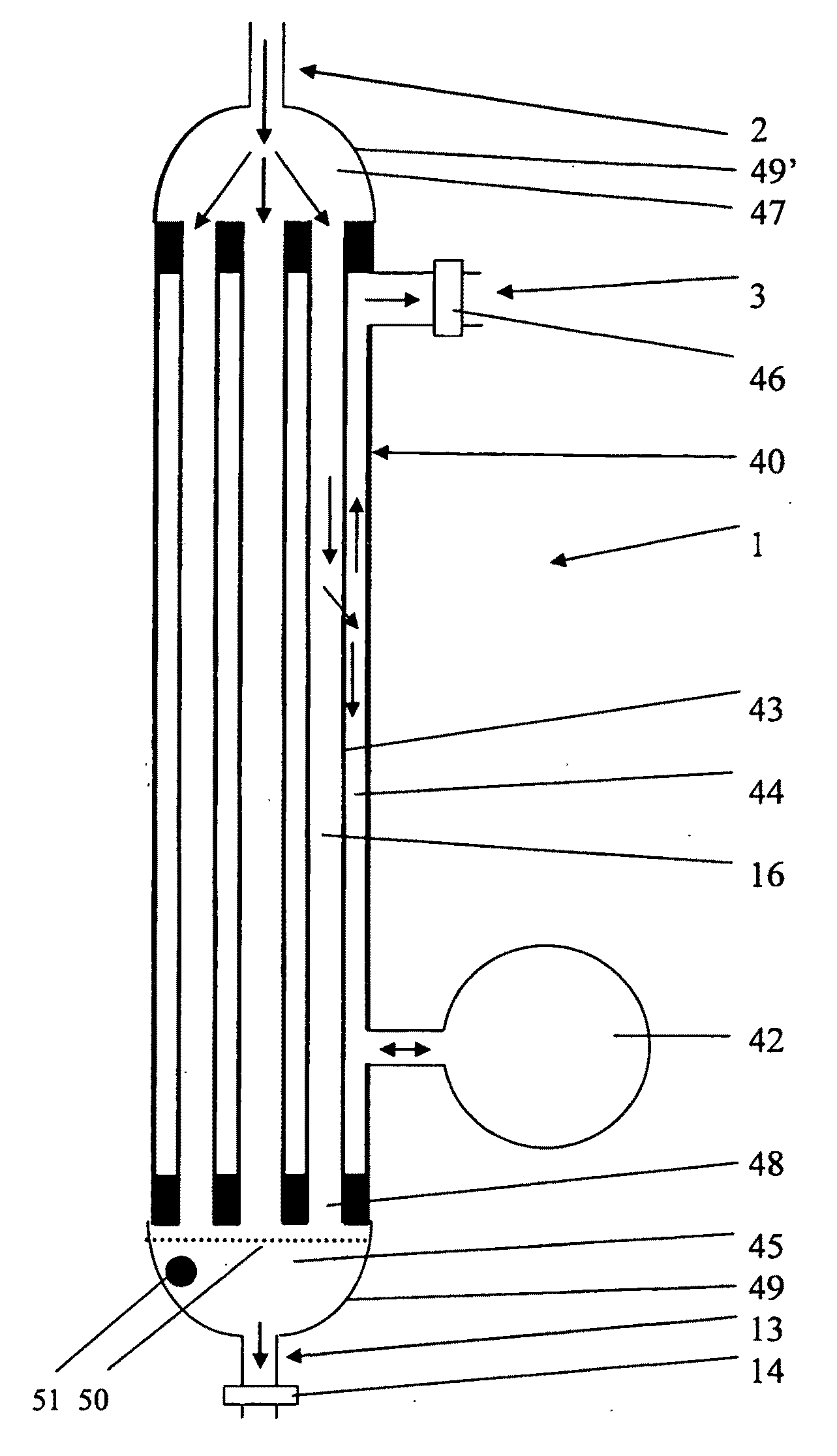
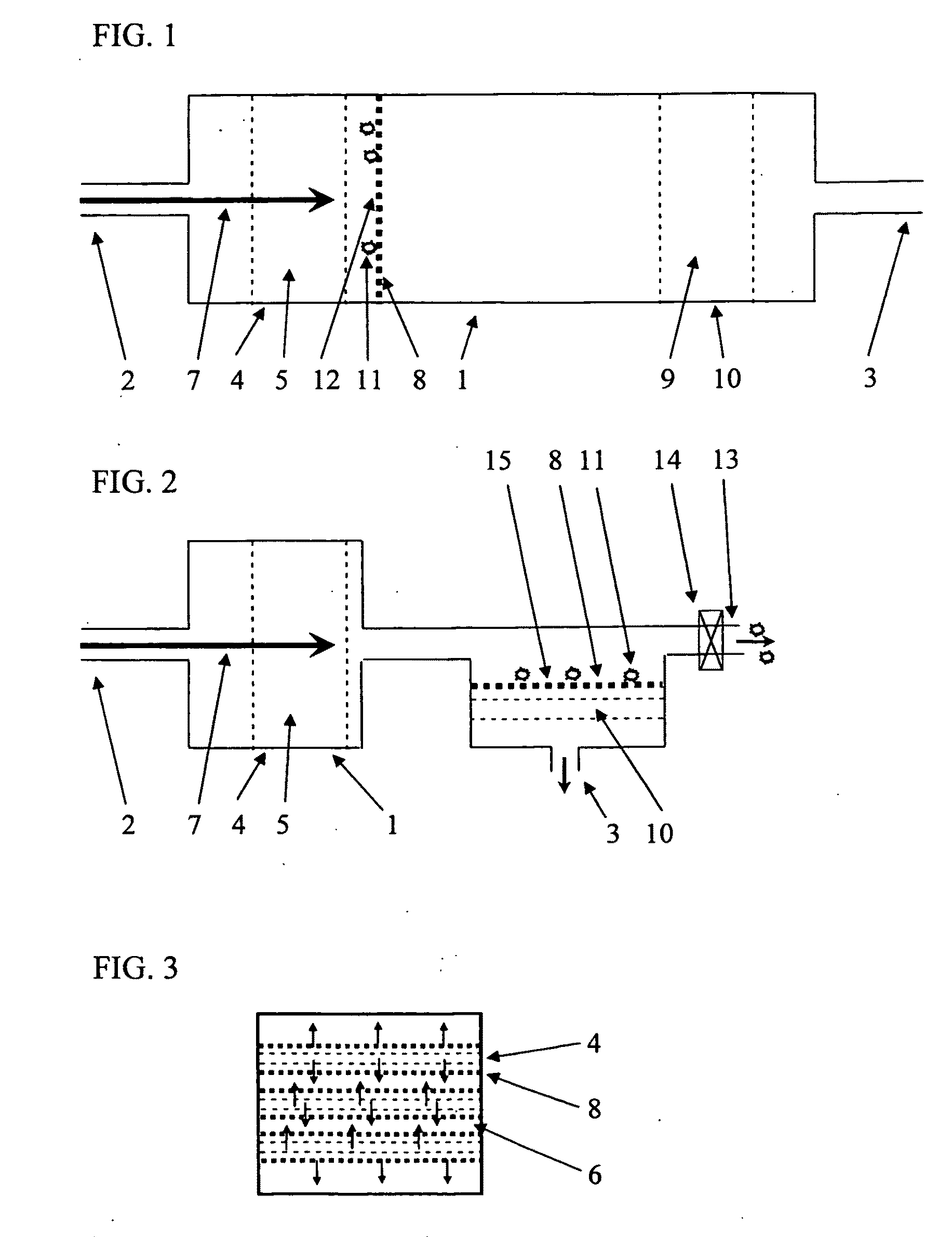
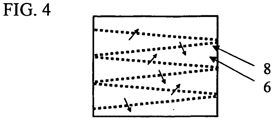
[0101]FIG. 1 illustrates a principle of the invention. The fluid filtration device 1 has a fluid inlet 2 and a fluid outlet 3. The fluid is preferably liquid, but the invention is of general nature and may be used for gases, aerosols or vapours as well. Downstream of the fluid inlet 2 is a chamber 4 where an antimicrobial substance 5, preferably halogen, is provided. The source could be a halogenated liquid or gas that is provided at a suitable rate to the fluid through the device. However, preferred is a halogenated resin through which the fluid flows, which is indicated by arrow 7. After the step of adding a halogen to the fluid, the fluid traverses a microporous filter 8, preferably a membrane, before the fluid leaves the device through the fluid outlet 3. Optionally, the device 1 also has a halogen absorber 9 in a third chamber 10. Material 11, such as bacteria, virus, and other material is held back at the microporous inlet surface of the wall 12 of the membrane 8. In a vertica...


PUM

PropertyMeasurementUnit
diameteraaaaaaaaaa
diameteraaaaaaaaaa
diameteraaaaaaaaaa

Abstract

A method for filtration of fluid, primarily liquid, with fluid filtration device haying a fluid inlet and a fluid outlet and a fluid path between the inlet and the outlet through a microporous filter with a pore size adapted for filtering bacteria or bacteria and virus by mechanical particle size separation. The filtration device comprises further an antimicrobial source adding antimicrobial substance to the fluid in the fluid path between the fluid inlet and the inlet surface of the microporous filter. The fluid filtration device is provided with a design flow through the device, the design flow assuring a proper filtration of the fluid flowing through the device with a cleaned fluid at the flow outlet. The antimicrobial source, for example a halogen source, is configured to release the antimicrobial substance at a low elution rate that is not high enough for killing substantially all the microbes in the fluid during the time it takes the fluid to flow through the device at the design flow, but which is high enough for prevention of a biofilm in the long term.

Description

FIELD OF THE INVENTION[0001]The present invention relates to a method for filtration of fluid, primarily liquid, with fluid filtration device. The filtration device has a fluid inlet and a fluid outlet and a fluid path between the inlet and the outlet through a microporous filter with a pore size adapted for filtering bacteria or bacteria and virus by mechanical particle size separation. The filtration device comprises further an antimicrobial source adding antimicrobial substance to the fluid in the fluid path between the fluid inlet and the inlet surface of the microporous filter.BACKGROUND OF THE INVENTION[0002]Typically, household water purification equipment for elimination of microbes in drinking water can follow 2 paths: Chemical deactivation or mechanical filtration.[0003]In case of chemical deactivation, usually, halogenated media, such as Chlorine or Iodine, is being used. For example, in water purification tools, where iodine sources are used, iodine and iodide is release...

Claims


Application Information

Patent Timeline
Patent Type & Authority Applications(United States)
IPC IPC(8): C02F1/76C02F1/68A47G21/18
CPCA47G21/188B01D61/147B01D61/18B01D63/02B01D63/082B01D65/08B01D2311/04B01D2313/40B01D2313/44B01D2321/168C02F1/002C02F1/283C02F1/444C02F1/505B01D61/16B01D61/145B01D2311/2626B01D2311/2649A47G21/18B01D29/66C02F1/68C02F1/76
Inventor VESTERGAARD FRANDSEN, MIKKEL
Owner VESTERGAARD FRANDSEN AS
Why Eureka
Try Eureka