Filter set for observing fluorescence radiation in biological tissue

a filter set and fluorescence radiation technology, applied in the field of filter sets for observing fluorescent radiation, can solve the problems of not being sufficiently localized in the surrounding tissue, not being sufficiently differentiated from healthy tissue, and outshone by excitation radiation, so as to achieve optimal adaptation to excitation bands

Active Publication Date: 2010-02-25
CARL ZEISS MEDITEC AG
View PDF11 Cites 19 Cited by
  • Summary
  • Abstract
  • Description
  • Claims
  • Application Information

AI Technical Summary

Benefits of technology

[0051]According to a further embodiment a medical optical system for observing fluorescent radiation in biological tissue comprises an illumination system having a light source and illumination optics, to illuminate the tissue with illumination radiation, the medical optical system further comprising an imaging system having imaging optics, to guide radiation emanating from the tissue to an image plane. Thereby, the light source of the illumination system provides light exclusively out of the first wavelength transmission range of the previously described filter set. By using such a light source for example an optimal adaptation to excitation bands of a fluorescent dye is possible. Therein, the light source may, for example, be a laser or a light emitting diode. The imaging system then comprises at least one filter holder with the at least one observation filter of the previously described filter set.

Problems solved by technology

Since the intensity of the fluorescent radiation is usually more than one order of magnitude smaller than the intensity of the excitation radiation, there is the risk that the fluorescent radiation is outshone by the excitation radiation.
Otherwise there is for example the risk that, although tumour tissue may be observed using the fluorescent radiation, it may not be sufficiently localized in the surrounding tissue and that it may not be sufficiently differentiated from healthy tissue.
In particular, the known solutions are suitable to only a limited extent for fluorescent dyes for which the excitation band and the fluorescent band lie very close to each other or partially overlap (as is for example the case for Hypericin).

Method used


Image

  • Filter set for observing fluorescence radiation in biological tissue
  • Filter set for observing fluorescence radiation in biological tissue
  • Filter set for observing fluorescence radiation in biological tissue

Examples


first embodiment

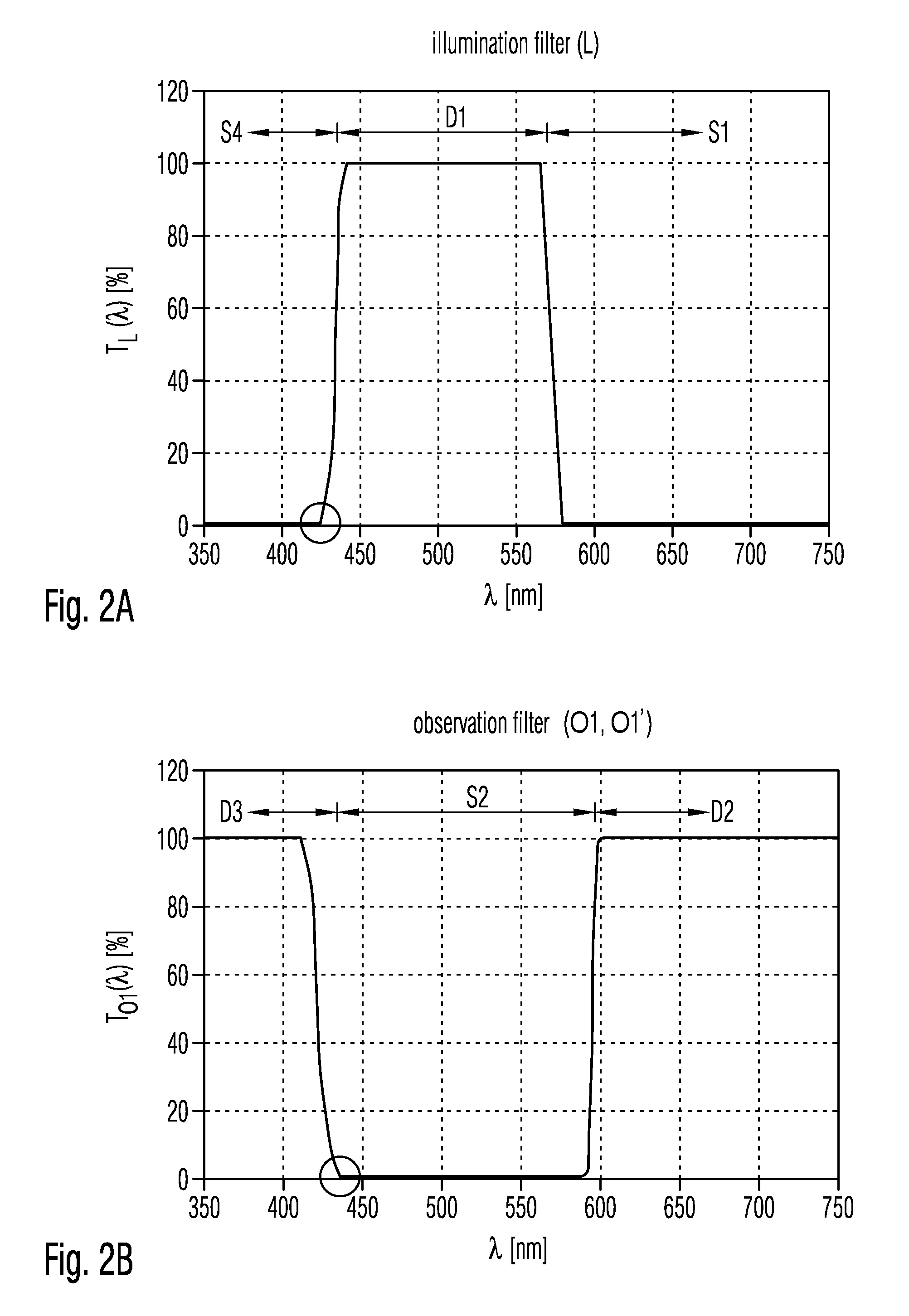
[0087]The first embodiment is thus based on a purposeful overlap of flanks of the transmittances TL(λ), TO1(λ) for wavelengths λ of the illumination filter L and the observation filter O1, O1′.

[0088]In the following a second embodiment of the filter set is explained in detail referring to FIGS. 3A to 3C. In this second embodiment the afore described second illumination filter L′ is used.

[0089]Also in this embodiment the observation filter O2, O2′ further has a third wavelength transmission range D3′ comprising wavelengths λ shorter than 485 nm and thus for wavelengths λ shorter than those comprised in the second wavelength blocking range S2′. The transmittance TO2(λ) for wavelengths λ of the observation filter O2, O2′ in the third wavelength transmission range D3′ in a spectral band between 435 nm and 485 nm thereby is greater than 0.001, and is smaller than 0.001 in the second wavelength blocking range D2′ and thus between 485 nm and about 580 nm. Thus, the second wavelength blocki...

second embodiment

[0094]Thus, the second embodiment is based on a purposefully spectrally broad superposition of the first wavelength transmission range D1 of the illumination filter L′ and the third wavelength transmission range D3′ of the observation filter O2, O2′.

[0095]An observation filter O2, O2′ having the transmittance TO2(λ) for wavelengths λ shown in FIG. 3B is purchasable in the year 2008 under the denomination “Brightline HC 620 / 52” from the company SLMROCK, 3625 Buffalo Road, Suite 6, Rochester, N.Y. 14624, USA.

[0096]In both preceding embodiments a product of the transmittance TL(λ), TL′(λ) for wavelengths λ of the respective illumination filter L, L′ with the transmittance TO1(λ), TO2(λ) for wavelengths λ of the respective observation filter O1, O1′, O2, O2′ in a spectral range between the first wavelength transmission range D1 and the second wavelength transmission range D2 of more than 5 nm of spectral width is always smaller than 0.01 and in particular always smaller than 0.001.

[0097...


PUM


Abstract

A filter set for observing fluorescent radiation in biological tissue includes at least one illumination filter and at least one observation filter. The at least one illumination filter is arrangeable in an illumination system of an optical system. The at least one least one observation filter is arrangeable in an imaging system of the optical system.

Description

CROSS-REFERENCES TO RELATED APPLICATIONS[0001]This application claims priority to German Patent Application DE 10 2008 034 008.1, filed Jul. 21, 2008. The disclosure of DE 10 2008 034 008.1 is hereby incorporated by reference in its entirety for all purposes.BACKGROUND OF THE INVENTION[0002]1. Field of the Invention[0003]The invention relates to a filter set for observing fluorescent radiation (also called fluorescence radiation; radiation caused by fluorescence) in biological tissue and thus relates to observing emission of light of an endogenous (produced naturally in the body) or exogenous fluorophore due to an excitation using radiation. Herein, fluorophore in general refers to a substance for which fluorescence (emission of fluorescent radiation) arises due to an excitation. The observation may optionally be performed in a living organism and thus in vivo or in an artificial environment (outside of living organisms, for example in vitro). Further, the invention relates to a med...

Claims


Application Information

Patent Timeline
Patent Type & Authority Applications(United States)
IPC IPC(8): G01J1/58G02B5/22
CPCA61B5/0059G01J3/4406G01J2003/1213G01N21/6428G01N21/6458G02B21/16G01N2021/6419G01N2021/6421G01N2021/6471G02B5/20G02B5/208G01N21/6486
Inventor STEFFEN, JOACHIMHAUGER, CHRISTOPH
Owner CARL ZEISS MEDITEC AG
Why Eureka
Try Eureka