Fuel pump device

a fuel pump and pump body technology, applied in the direction of liquid fuel engines, machines/engines, positive displacement liquid engines, etc., can solve the problems of certain fuel leakage, increased fuel leakage between pistons and cylinders, and fuel leakage itself, so as to reduce the level of fuel leakage flow, simple design, and high efficiency

Active Publication Date: 2010-02-25
SCANIA CV AB
View PDF5 Cites 9 Cited by
  • Summary
  • Abstract
  • Description
  • Claims
  • Application Information

AI Technical Summary

Benefits of technology

[0005]The object indicated above is achieved with the fuel pump device of the kind mentioned in the introduction which is characterised by the features indicated in the characterising part of claim 1. Such a temperature-regulating means makes it possible for the pressure-generating components of the fuel pump to maintain a temperature within the predetermined temperature range substantially independently of the load of the fuel pump. Making the temperature range rather narrow makes it possible for the temperature of the components to vary relatively slightly and for their thermal expansion to be therefore very small. The difference in thermal expansion between the pressure-generating components thus becomes substantially negligible. The existing clearance between the pressure-generating components can therefore be kept at a substantially constant level when they are at a temperature within the predetermined temperature range. As the clearance remains substantially unchanged during operation of the fuel pump, the pressure-generating components can be dimensioned so that said clearance will be very small within the predetermined temperature range. This makes it possible to maintain an extremely low level of fuel leakage flow. The fuel pump can therefore operate at high efficiency even when very high fuel pressures are generated.
[0006]According to an embodiment of the present invention, said temperature-regulating means comprises a medium adapted to flowing through the fuel pump in a passage which extends through said region. Leading a medium at a suitable temperature through the passage results in heat exchange between the medium and the pressure-generating components situated in the region. If the temperature of the components is about to rise to a level above a maximum acceptable value within the temperature range, a flow of medium at a suitable temperature is led through the passage to cool the components. If conversely the temperature of the components in the region is about to drop to a level below a minimum acceptable value within the temperature range, a flow of medium at a suitable temperature is led through the passage to warm the components. Said temperature-regulating means may comprise a valve by which it is possible to control the flow of the medium through said passage. The fact that the flow of medium through the region can be regulated makes it likewise easy to regulate the cooling or warming effect imparted to the pressure-generating components. With advantage, said temperature-regulating means comprises a temperature sensor so positioned that it detects a temperature which is related to the temperature in the region. The current temperature in the region can thus be used as a parameter for regulating the temperature in the region. The fuel pump device preferably comprises a control unit which receives this information and controls the valve so that it supplies the medium in an amount which makes it possible to maintain a temperature in the region within the predetermined temperature range.
[0007]According to another embodiment of the present invention, said medium led to the fuel pump is adapted to being at a temperature within said temperature range. An abundant flow of medium through the passage results in a temperature in the region which substantially corresponds to the temperature of the medium. A medium at such a temperature can thus be used both to provide cooling of the pressure-generating components if they are at too high a temperature and to warm them if they are at too low a temperature. Said medium may be coolant which is also used in the cooling system for cooling a combustion engine. Using coolant already existing in a vehicle for cooling the fuel pump means that the temperature-regulating means can be of quite simple design and comprise relatively few components. It is also possible, however, to use other existing liquids in a vehicle for cooling the fuel pump, e.g. diesel oil, petrol etc. It is also possible to use an entirely separate temperature-regulating means which has a circulating medium of its own for regulating the temperature in said region of the fuel pump.
[0008]According to another embodiment of the present invention, said temperature-regulating means is adapted to maintaining the temperature in said region within a temperature range in which the difference between the maximum and minimum values of the temperature range is not more than 10° C. In this case, the temperature range is so narrow that the pressure-generating components are subject to very little thermal expansion within the temperature range. Such a temperature range may for example extend from 30° C. to 40° C. The temperature range should have a relatively low minimum temperature, otherwise the clearance between the pressure-generating components becomes so small that it will be difficult to start the fuel pump when there is a cold ambient temperature. Cold starts of the fuel pump can be facilitated by providing an electric heater to preheat the pressure-generating components before the fuel pump starts.
[0009]According to another embodiment of the present invention, the pressure-generating components are at least partly made of different materials. The pressure-generating component which comprises the pressure-generating surface is with advantage made of very wear-tolerant material, which may be ceramic material. The other pressure-generating component which constitutes the space in which the first pressure-generating component is adapted to moving is with advantage made of metal material. Said temperature-regulating means thus keeps the pressure-generating components at a temperature within a relatively narrow temperature range. This makes it possible to use different materials for the respective pressure-generating components, since they are subject to substantially no thermal expansion during operation of the fuel pump.
[0010]According to another embodiment of the present invention, the second pressure-generating component is a cylindrical space and the first pressure-generating component is a piston arranged for movement within the cylindrical space. The fuel pump, which comprises pressure-generating components in the form of a piston and a cylinder, can easily effect pressurisation of fuel to a high pressure. Said passage comprises with advantage a space which surrounds the cylindrical space. The temperature-regulating medium can thus flow round the pressure-generating components. The medium can thereby, when necessary, provide very effective cooling or warming of the pressure-generating components.

Problems solved by technology

When a high-pressure pump pressurises the fuel, a certain fuel leakage inevitably occurs at the clearance between the pressure-generating components of the fuel pump, which usually take the form of a piston and a cylinder.
The increasing clearance leads also to the fuel leakage between piston and cylinder increasing with temperature.
The fuel leakage itself also gives rise to further heating of the piston and the cylinder when fuel flows at high velocity through the clearance in contact with the surfaces of the piston and the cylinder.
This further heating of the piston and the cylinder increases the clearance further, resulting in still greater fuel leakage.
During operation of conventional high-pressure pumps there is therefore relatively great heating of the piston and the cylinder, resulting in a large fuel leakage flow and reduced efficiency of the fuel pump.
The high fuel pressure may itself also cause expansion of the cylinder with consequently increased clearance between the surfaces of the piston and the cylinder.

Method used


Image

  • Fuel pump device
  • Fuel pump device
  • Fuel pump device

Examples


Embodiment Construction

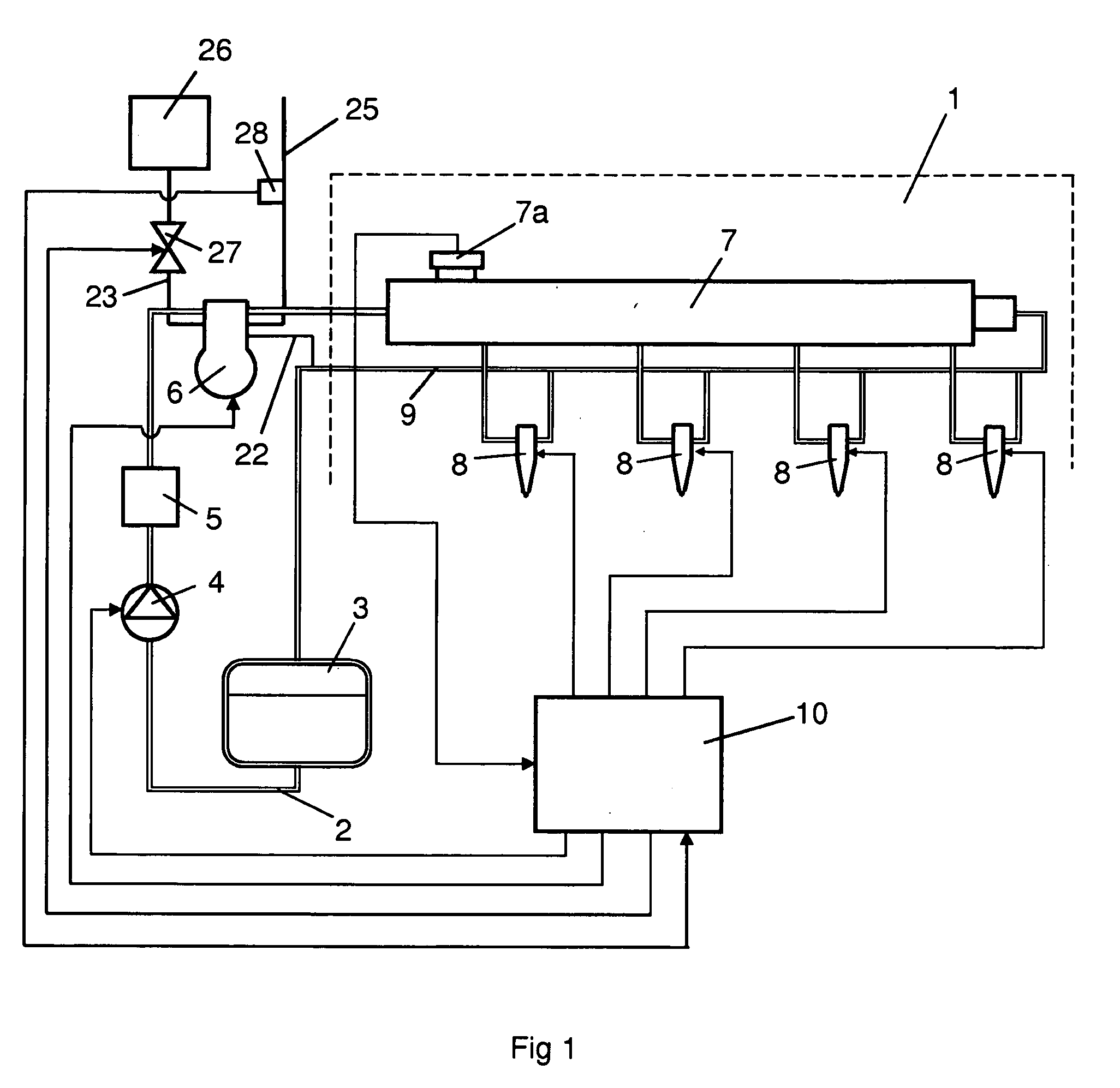
[0014]FIG. 1 depicts an injection system for injecting fuel at a very high pressure in a combustion engine here exemplified as a diesel engine 1. Injecting the fuel at a very high pressure may reduce discharges of emissions from the diesel engine 1. The injection system and the diesel engine 1 may be fitted in a heavy vehicle. The injection system comprises a fuel line 2 for supplying fuel from a fuel tank 3 to the respective cylinders of the diesel engine 1. A first fuel pump 4 is arranged in the fuel line 2 to transfer fuel from the fuel tank 3 to a high-pressure pump 6 via a filter 5. The high-pressure pump 6 is adapted to pressurising the fuel so that it enters at a high pressure an accumulator tank 7 which takes the form of a so-called “Common Rail”. Injection means 8 are arranged at each of the connections between the accumulator tank 7 and the respective cylinders of the diesel engine 1. A return line 9 is adapted to leading fuel not burnt in the diesel engine 1 back to the f...


PUM


Abstract

A fuel pump device includes a fuel pump in which pressure-generating components in the form of a movable piston movable through a cylinder in the fuel pump together are operable to pressurize the fuel in a chamber exposed to the components to high pressure. To prevent the clearance between the pressure-generating components from increasing with increased heating of the fuel pump and to maintain a predetermined clearance between the piston and the surrounding cylinder, a temperature-regulator maintains a temperature within a predetermined temperature range in a region of the fuel pump which includes the clearance and at least portions of the pressure-generating components.

Description

BACKGROUND TO THE INVENTION, AND STATE OF THE ART[0001]The present invention relates to a fuel pump device according to the preamble of claim 1.[0002]One way of reducing discharges of emissions from diesel engines is to inject the fuel at a very high pressure. A so-called “Common Rail” system is commonly used for effecting injection at a high pressure in the combustion spaces of a diesel engine. A Common Rail system comprises a high-pressure pump which pumps fuel at a high pressure to an accumulator tank (“Common Rail”). The fuel in the accumulator tank is intended to be distributed to all the cylinders of the combustion engine. Fuel from the accumulator tank is injected into the combustion spaces of the respective cylinders by electronically controlled injection means.[0003]When a high-pressure pump pressurises the fuel, a certain fuel leakage inevitably occurs at the clearance between the pressure-generating components of the fuel pump, which usually take the form of a piston and ...

Claims


Application Information

Patent Timeline
Patent Type & Authority Applications(United States)
IPC IPC(8): F04B49/00
CPCF02M53/00F02M59/102F02M59/445F04B53/008F02M2200/24F04B1/0421F02M63/0001F02M59/442F02M63/0225
Inventor HOKKANEN, VESA
Owner SCANIA CV AB
Why Eureka
Try Eureka