Dynamic Cylinder Deactivation with Residual Heat Recovery

a technology of residual heat recovery and cylinder deactivation, which is applied in the direction of electric control, fuel injection control, machines/engines, etc., can solve the problems of dcd not disassembly and sealing of the valves, and achieve the effect of higher engine fuel conversion efficiency

Inactive Publication Date: 2010-03-04
ZHAO YUANPING +1
View PDF16 Cites 216 Cited by
  • Summary
  • Abstract
  • Description
  • Claims
  • Application Information

AI Technical Summary

Benefits of technology

[0013]The present invention is Dynamic Cylinder Deactivation control method for internal combustion engine, or DCD for short. DCD is an electronic based cylinder deactivation method. Controlled by electronic circuits and microcontroller, DCD deactivates all the cylinders inside the engine dynamically and in a balanced way. That is, all the cylinders inside the engine would be working in an intermittent mode, being activated and deactivated alternatively. The result would be not only a well balanced engine thermal condition under which engine performance could be kept best, but also the residual heat recovery by engine thermodynamic expansion during the deactivation cycles. Based on all of these benefits, we could expect DCD would bring us higher engine fuel conversion efficiency than traditional sealed-valves cylinder deactivation.
[0016]The balance of the deactivation pattern is very important. The balance in engine timing sequence would result smooth mechanical operation. The balance in deactivation duty cycle would cause balanced cylinder thermal condition and balanced cylinder temperature. All these balances would keep engine operating in a perfect condition, thus providing higher fuel conversion efficiency.
[0018]To engine users and automobile consumers, the benefits of cylinder deactivation is simply reduced fuel consumption and improved fuel economy. It also helps to reduce engine emissions and CO2 discharge. Saving fuel means energy conservation, which would help to solve energy problem and ease the crude oil price. It also has positive contribution to the public communities by reducing global warming and greenhouse effects.

Problems solved by technology

DCD would not disable and seal the valves like what is being done in all traditional sealed-valves cylinder deactivation solutions.

Method used


Image

  • Dynamic Cylinder Deactivation with Residual Heat Recovery
  • Dynamic Cylinder Deactivation with Residual Heat Recovery
  • Dynamic Cylinder Deactivation with Residual Heat Recovery

Examples


Embodiment Construction

[0032]Reference will now be made in detail to the presently preferred embodiments of the invention, examples of which are illustrated in the accompanying drawings.

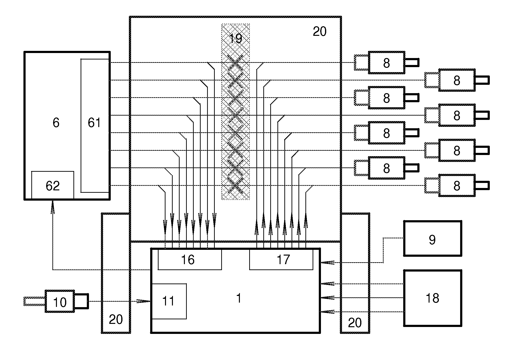
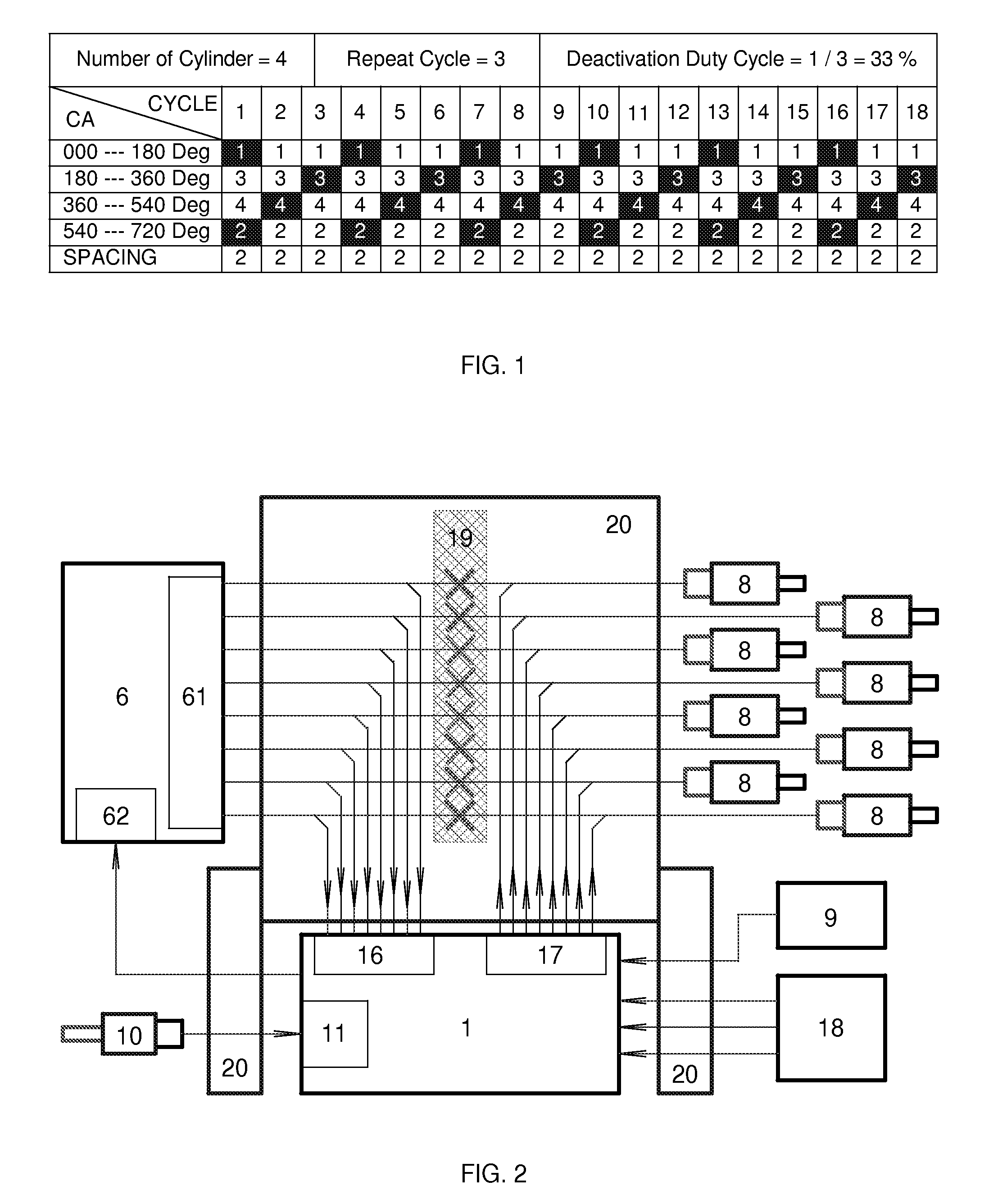
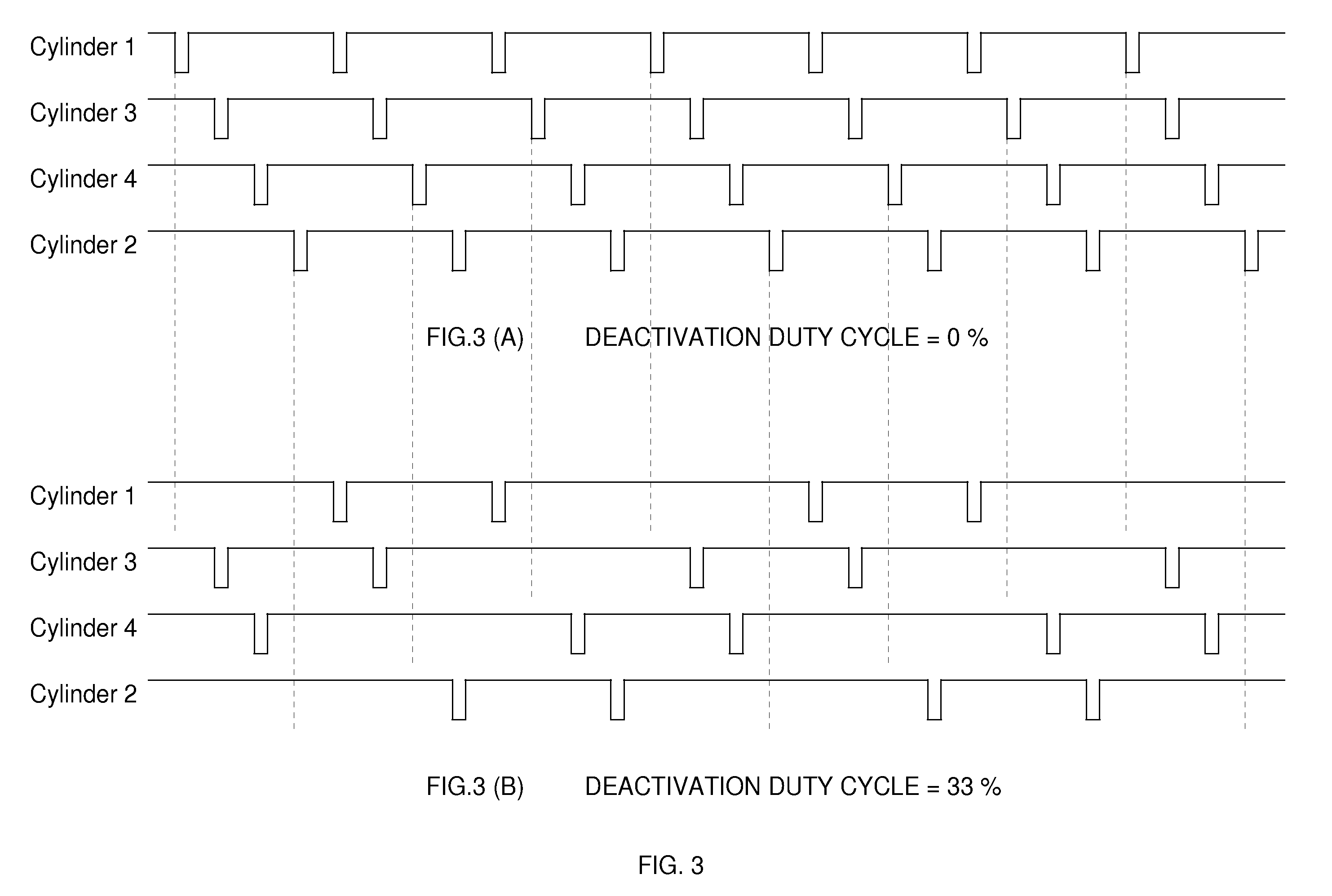
[0033]The present invention is directed to Dynamic Cylinder Deactivation control method for internal combustion engine, or DCD for short. DCD is an electronic based cylinder deactivation method. Controlled by electronic circuits and microcontroller chips, DCD deactivates all the cylinders inside the engine dynamically and in a balanced way. That is, all the cylinders inside the engine would be working in an intermittent mode, being activated and deactivated alternatively. The result would be not only a well balanced engine thermal condition under which engine performance could be kept best, but also the residual heat recovery by engine thermodynamic expansion during the deactivation cycles. Based on all of these benefits, we could expect DCD would bring us higher engine fuel conversion efficiency than traditional sealed-va...


PUM


Abstract

Cylinder deactivation is a proven solution to improve engine fuel efficiency. The present invention is related to Dynamic Cylinder Deactivation (DCD) solution to conventional internal combustion engine. DCD is an energy saving method based on engine thermodynamics and residual heat recovery. It deactivates all the cylinders within the engine alternatively and dynamically, totally different from traditional sealed-valves cylinder deactivation solutions. DCD has many advantages over traditional sealed-valves cylinder deactivation. Thermodynamic efficiency gain, residual heat recovery, high Lambda and “Air-Hybrid” are the most attractive features of DCD. DCD also makes engine displacement variable.

Description

RELATED PATENT APPLICATION[0001]This application claims the benefit of priority of U.S. Provisional Application No. 61 / 092,752 filed on Aug. 29, 2008, entitled “Dynamic Cylinder Deactivation with Residual Heat Recovery” and which is incorporated in its entirety herein.FIELD OF THE INVENTION[0002]The present invention relates to internal combustion engine with variable displacement control by cylinder deactivation, particularly to Dynamic Cylinder Deactivation (DCD) control method of internal combustion engine, which deactivates all the cylinders inside the engine alternatively, dynamically and in a way of keeping thermal balance and mechanical balance between cylinders while keeping best engine overall torque balance.BACKGROUND OF THE INVENTION[0003]The present invention relates to Dynamic Cylinder Deactivation (DCD) solution to conventional internal combustion engine. DCD is an engine cylinder deactivation solution based on engine thermodynamics and residual heat recovery. It is an...

Claims


Application Information

Patent Timeline
Patent Type & Authority Applications(United States)
IPC IPC(8): F02D7/00
CPCF02D17/02F02D41/0085F02D2041/2027F02D41/1497F02D41/0087
Inventor ZHAO, YUANPINGZHOU, BIYUN
Owner ZHAO YUANPING
Why Eureka
Try Eureka