Direct current motor

motor body technology, applied in the direction of windings, mechanical energy handling, dynamo-electric components, etc., can solve the problems of difficult to become an effective solution means for flattening a direct current motor, electric noise may occur, and the work involved in assembling a choke coil in a steric manner with respect to the above conventional art is extremely difficult, so as to reduce the size of the direct current motor and the effect of flattening the direct current motor

Active Publication Date: 2010-03-04
MITSUBA CORP
View PDF6 Cites 17 Cited by
  • Summary
  • Abstract
  • Description
  • Claims
  • Application Information

AI Technical Summary

Benefits of technology

[0021]According to the present invention, since the constitution of the direct current motor has six poles, nine slots, and nine segments, and the segments with the same polarity are short-circuited by short-circuiting members, it is possible to make the brushes to be installed a pair. Moreover, since the pair of brushes is arranged so as to be mutually point symmetric centered on the rotating shaft, it is possible to achieve a flattening of the direct current motor compared to the case of the brushes being arranged at 90 degrees relative to each other.
[0022]Also, according to the present invention, since the coils are wound with the concentrated winding system, compared to a conventional single winding system, it is possible to reduce an enlargement in size of the armature coil accompanying the winding of the coils. Therefore, it is possible to achieve a further reduction in size of the direct current motor.
[0023]Moreover, according to the present invention, since it is possible to divide the teeth from the armature core, it is possible to wind the coils on every tooth. For this reason, it is possible to easily wind the coils on the teeth, and it is possible to improve the working efficiency. Also, since it is possible to ensure sufficient space for winding the coils around the teeth, it is possible to improve the space factor of the armature coil.
[0024]According to the present invention, since the constitution of the direct current motor has six poles, nine slots, and nine segments, and by short-circuiting the segments with the same polarity with short-circuiting members the pair of brushes are arranged with a mutual interval of 60 degrees in the circumferential direction, it is possible to make the brush holder small compared to the case of oppositely arranging the pair of brushes. Therefore, it is possible to downsize the direct current motor.
[0025]Furthermore, when using a brush holder of almost the same size as a conventional brush holder, it is possible to ensure space between the brushes of the brush holder and the power feeding portions and on approximately the same plane as the brushes. For this reason, it becomes possible to arrange noise prevention elements in this space. Therefore, it is possible to easily attach noise prevention elements in the vicinity of the brushes that are the generation source of electrical noise without enlarging the brush holder.
[0026]Also, according to the present invention, since the coils are wound by the concentrated winding system, compared to the conventional single winding system, it is possible to reduce an enlargement in size of the armature coil accompanying the winding of the coils. Therefore, it is possible to achieve a further reduction in size of the direct current motor.

Problems solved by technology

Also, when the brushes are separated from the segments during rotation of the armature, due to the release of magnetic energy that is stored in the coil, electrical discharge occurs between the brushes and the segment, and thereby electrical noise may occur.
For this reason, although it may become a solution means effective for attaining the downsizing of a direct current motor, there is the problem of it being difficult to become an effective solution means for flattening of a direct current motor.
Also, in the flattened direct current motor as in Patent Document 2 and Patent Document 3, the work involved in assembling a choke coil in a steric manner with respect to the brushes with the above conventional art is extremely difficult, and when production efficiency is taken into consideration, there is the problem of it being difficult to realize in practical terms.

Method used


Image

  • Direct current motor
  • Direct current motor
  • Direct current motor

Examples


first embodiment

[0070]Next, the present invention shall be described with reference to FIGS. 1 to 4.

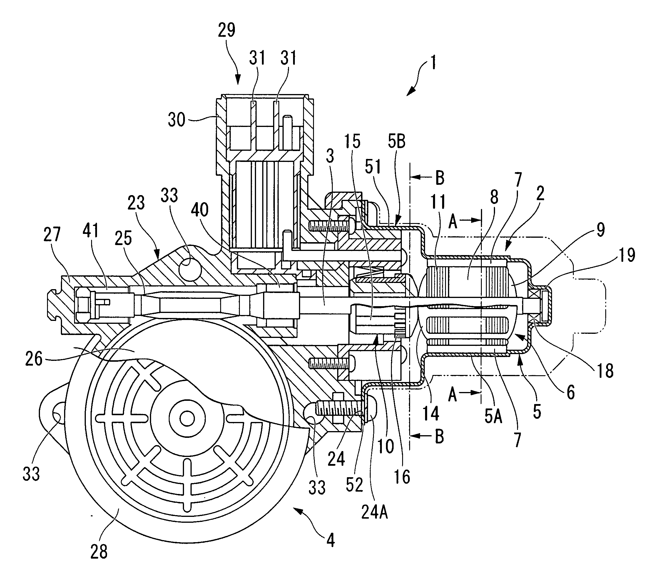
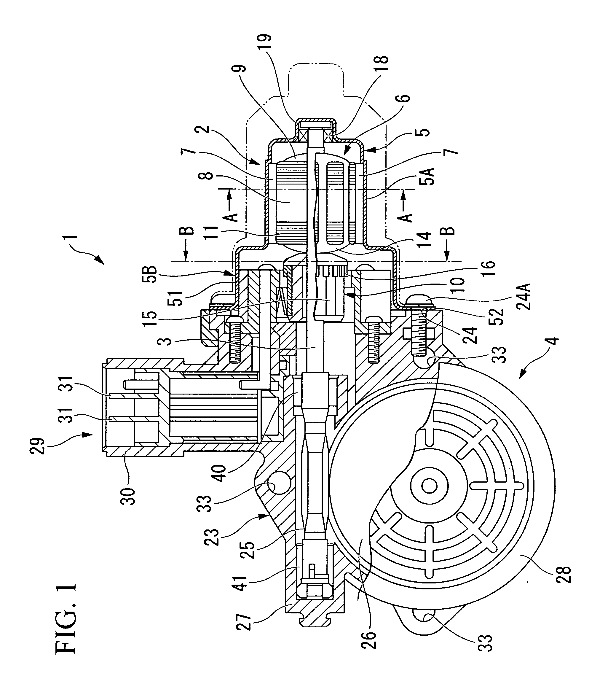
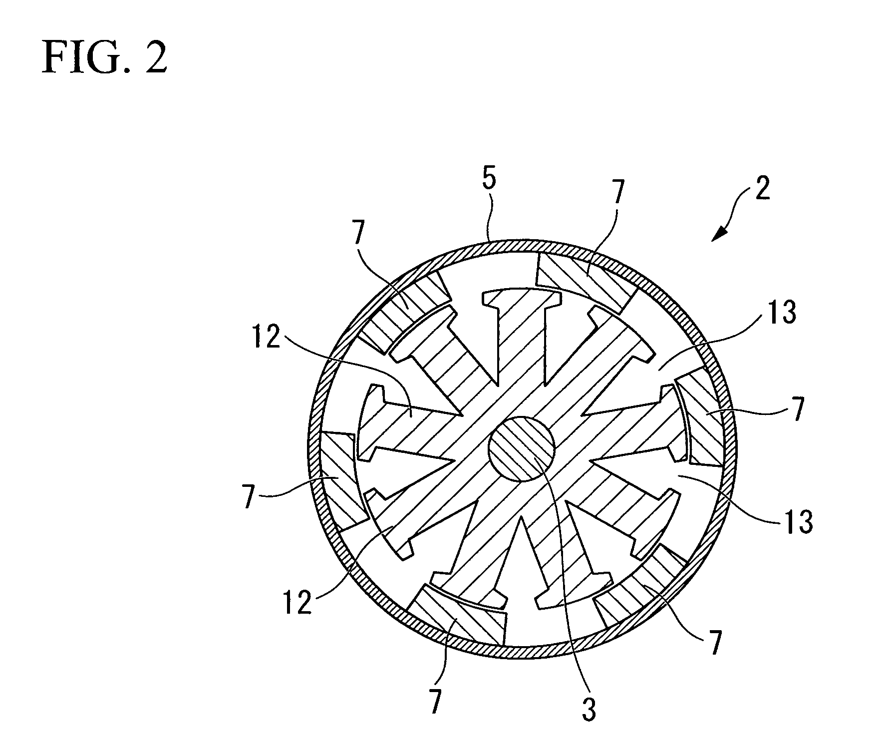
[0071]FIG. 1 is a cross-sectional view that shows the constitution of a power window device 1 of a vehicle in which a direct current motor 2 according to the present invention is applied, FIG. 2 is a cross-sectional view along line A-A of FIG. 1, FIG. 3 is a plan view of an armature 6, and FIG. 4 is a cross-sectional view along line B-B of FIG. 1.

[0072]As shown in FIGS. 1 to 4, the power device 1 is provided with a direct current motor 2 and a worm gear reducer 4 that is coupled to a rotating shaft 3 of the direct current motor 2, and is installed in a vehicle door (not illustrated). Note that the chain double-dashed line drawn around the direct current motor 2 serves to show the contour of a conventional direct current motor for the purpose of comparison with the direct current motor 2 of the present invention.

[0073]The direct current motor 2 is constituted by arranging an armature 6 in a freely rot...

second embodiment

[0110]Next, the present invention shall be described based on FIG. 10 and FIG. 11.

[0111]The basic constitution of the second embodiment is the same as the first embodiment on the points of being a direct current motor of the three-phase concentrated winding system with six poles, nine slots and nine segments and an armature 6 arranged to freely rotate in a yoke housing 5 that has a permanent magnet 7, the point of the segments 15 having the same polarity being short circuited by the connecting wires 17, and the point of the pair of brushes 21 being mutually arranged at point symmetrical positions centered on the rotating shaft 3.

[0112]Here, as shown in FIG. 10 and FIG. 11, in an armature core 8, nine T-shaped tooth portions 81 that are detachable from an armature core body 80 are provided in a radial pattern on the armature core body 80 having an approximately cylindrical shape that is fixed to the rotating shaft 3 by being fitted from the outer side.

[0113]Nine connection recess por...

third embodiment

[0116]Next, the present invention shall be described based on FIG. 12 and FIG. 14.

[0117]The basic constitution of the third embodiment is the same as the first embodiment and the second embodiment on the points of being a direct current motor of the three-phase concentrated winding system with six poles, nine slots and nine segments and an armature 6 arranged to freely rotate in a yoke housing 5 that has a permanent magnet 7 and the point of the segments 15 having the same polarity being short circuited by the connecting wires 17.

[0118]Here, in the third embodiment, the brushes 21, 21 are arranged so that the interval θ between them in the circumferential direction becomes 60 degrees.

[0119]As shown in FIG. 12, a brush holder 20 is formed with an approximately oblong cross section so as to correspond to the flange housing portion 5B, and has a pair of plane walls 61A, 61B and a pair of curved walls 62A, 62B, with an insertion hole 64 that allows insertion of the commutator 10 formed ...


PUM


Abstract

A direct current motor with brushes in which an armature is provided with a rotating shaft that is supported by a yoke housing, an armature core that is fitted and fixed to a rotating shaft from the outer side, and a commutator that is provided on the rotating shaft adjacent to the armature core with nine segments arranged in the circumferential direction. The armature core has nine teeth that extend in the radial direction in a radial pattern and nine slots that are formed between the teeth and extend in the axial direction, the segments having the same polarity are connected with short-circuiting members, and a pair of brushes that make sliding contact with the segments is disposed so as to be mutually point symmetric centered on the rotating shaft. According to the preset invention, it is possible to effectively achieve flattening of the direct current motor.

Description

TECHNICAL FIELD[0001]The present invention relates to a direct current motor that is mounted in a vehicle. Priority is claimed on Japanese Patent Application No. 2006-316141, filed Nov. 22, 2006, and on Japanese Patent Application No. 2007-60355, filed Mar. 9, 2007, the contents of which are incorporated herein by reference.BACKGROUND ART[0002]In general, a direct current motor with brushes is often used as an electric motor mounted in a vehicle such as an automobile. This type of direct current motor is constituted such that permanent magnets of two or four poles are arranged at the inner circumferential surface of a cylindrical yoke housing and an armature on which an armature coil is wound is arranged on the inner surface of this permanent magnet so as to freely rotate. As the permanent magnet, a sintered ferrite magnet formed in the shape of a tile is used in many cases. The armature has an armature core that is externally fitted and fixed on the rotating shaft, and a plurality ...

Claims


Application Information

Patent Timeline
Patent Type & Authority Applications(United States)
IPC IPC(8): H02K23/04H02K5/24
CPCH02K5/04H02K5/148H02K23/38H02K13/10H02K23/30H02K7/1166
Inventor SHIODA, NAOKIKAWASHIMA, YOSHICHIKA
Owner MITSUBA CORP
Why Eureka
Try Eureka