
Polymer electrolyte fuel cell

Inactive Publication Date: 2010-03-04
NEC CORP
View PDF12 Cites 4 Cited by
  • Summary
  • Abstract
  • Description
  • Claims
  • Application Information

AI Technical Summary

Benefits of technology

[0027]A suppression layer (humidity maintenance layer), to suppress vaporization of generated water, is preferably provided on the oxygen electrode of the power generation part so that the produced water at the oxygen electrode is back-diffused to the fuel electrode to keep sufficient amount of water for the power generation.
[0029]According to the present invention, when the fuel cell is not operated (during storage), an opening portion(s) of the pored plate(s) of the high-concentration fuel tank is / are closed while the water fuel tank is not closed but opened. By such a storing method, the power generation part can be maintained humid by only water. It contributes to prevent the degradation of the power generation part during storage and makes it possible to shorten a start-up time after storage greatly.
[0031]By such a structure, the fuel tanks become detachable from the power generation part independently without liquid leakage and the storage method of the present invention can be realized by easy steps.

Problems solved by technology

Since the catalyst on an oxygen electrode of a proton-conductive polymer electrolyte fuel cell operated by the alcohol fuel is limited to a platinum-type catalyst that is highly active at the oxygen electrode, a cross-over phenomenon, in which an unreacted fuel migrates from the fuel electrode to the oxygen electrode and reacts with the platinum-type catalyst causing a voltage reduction and heat generation, becomes a problem when a highly-concentrated fuel is used.
However, the systems still have problems that they require complicated structures and a close control of the fuel concentration.
However, these systems have a problem that the cell voltage becomes unstable when ambient temperature of power-generator or load current changes significantly since the amount of diffused water from the oxygen electrode fluctuates correspondingly.

Method used


Image

  • Polymer electrolyte fuel cell
  • Polymer electrolyte fuel cell
  • Polymer electrolyte fuel cell

Examples


example 1

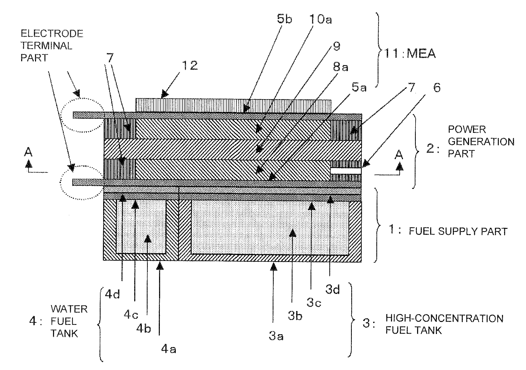
[0101]A polymer electrolyte fuel cell according to an example 1 of the present invention will be explained. A polymer electrolyte fuel cell of a single cell structure as shown in FIG. 1 is fabricated by the following method.

[0102]As for preparation of the oxygen electrode 10, at first a fine carbon particles-supported catalyst is prepared by making platinum fine particles in the range of 3 to 5 nm in particle diameter supported on carbon particles (Lion corporation, Ketjenblack EC600JD) at 55% in weight. Then an appropriate volume of 5 weight-% Nafion solution (Du Pont, DE521, Nafion is a registered trademark of Du Pont) is added into 1 g of the carbon particles-supported catalyst and stirred to obtain a catalyst paste for the oxygen electrode (which corresponds to the oxygen electrode catalyst layer 10a). The catalyst paste is applied on a collective electrode 5b made of metal in the amount of 1 to 8 mg / cm2 and dried into an oxygen electrode 10. A metal mesh (0.5 mm thick, porosity...

example 2

[0115]Generation powers of the generation cells of example 1 and comparison 1 were evaluated under constant current load conditions. FIG. 5 shows results of measured cell voltages under constant current load of 1 A, 1.5 A and 2 A in ten minuets each. As shown in FIG. 5, the generation cell according to the present invention can generate power constantly. On the other hand, in the case of the cell of comparison 1 according to a conventional structure, when the load current was changed, a rising speed of a cell voltage was slowed down and a fluctuation of the cell voltage was larger compared to the present invention. Thus a constant generation properties of the present invention has been proved even when a current load is changed.

example 3

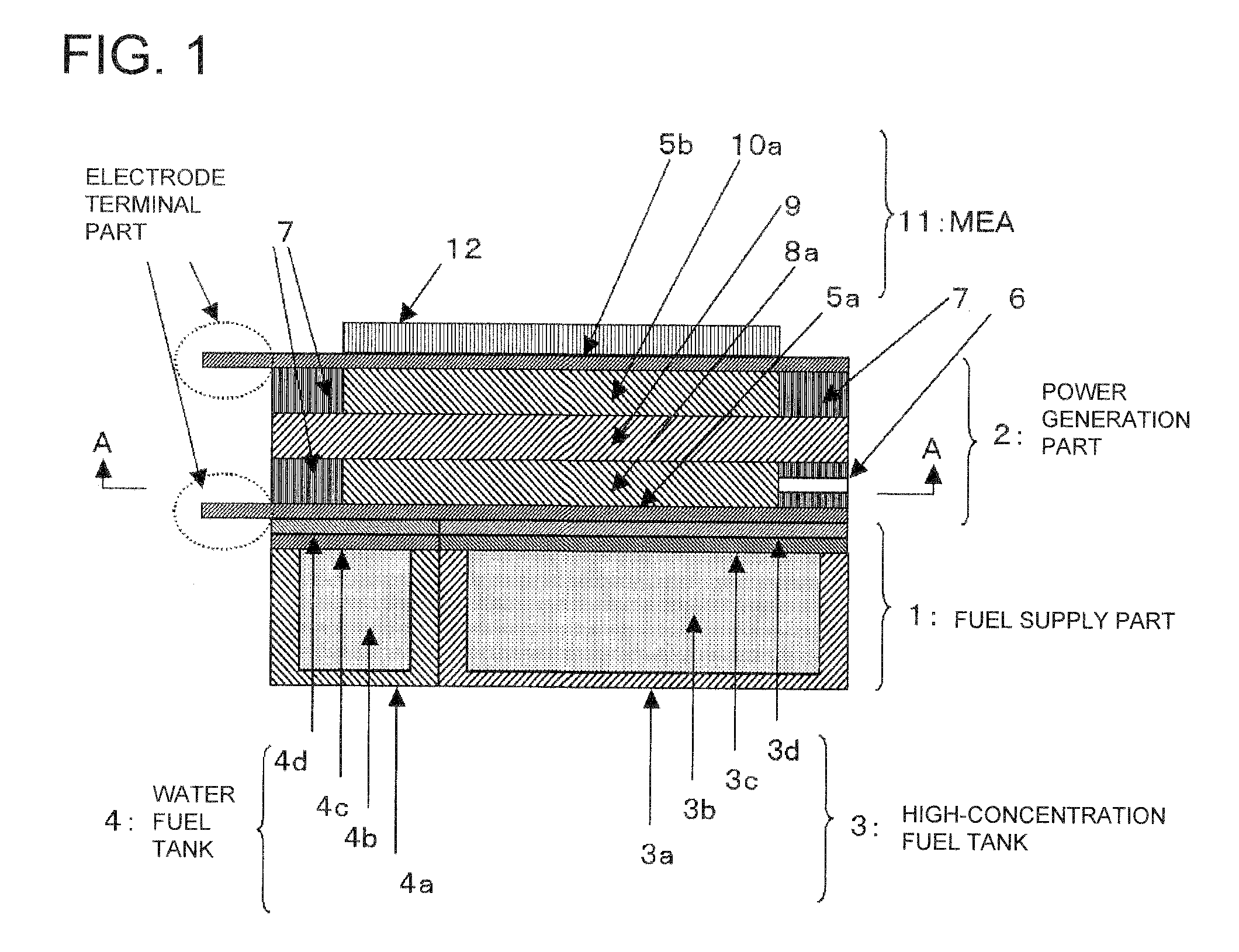
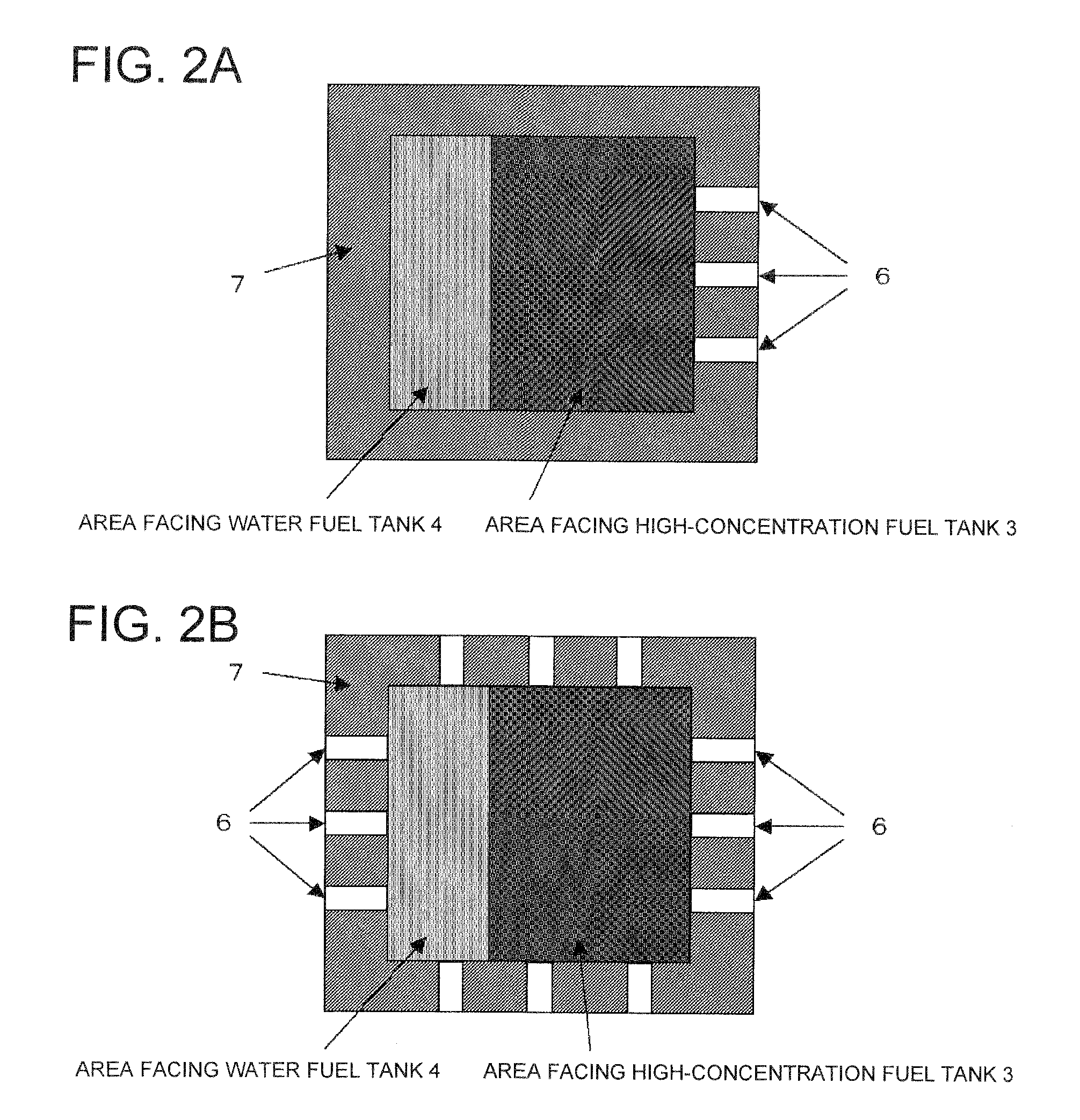
[0116]A generation power test was performed using the generation cell of example 1 and the generation cell of comparison 2. FIG. 6 shows changes of cell voltages versus time. The generation cell according to a conventional structure having CO2 gas discharge ports 6 equally spaced at four sides showed a larger reduction of its cell voltage versus time compared to the generation cell according to the present invention having CO2 gas discharge ports 6 formed only on the high-concentration fuel tank 3 side. The concentration of methanol in the water fuel tank 4, which was measured after generation, was about 3% v / v; however, the methanol concentration of a conventional structure, having CO2 gas discharge ports 6 formed evenly at four sides, was approximately 20% v / v. The reason of these differences was that the structure of the present invention, having CO2 gas discharge ports 6 formed only on the side of the high-concentration fuel tank 3, could restrict a back-flow of the fuel from th...


PUM

PropertyMeasurementUnit
Fractionaaaaaaaaaa
Concentrationaaaaaaaaaa
Volumeaaaaaaaaaa

Abstract

A polymer electrolyte fuel cell includes a power generation part as an electrolyte membrane-electrode assembly formed of a solid polymer electrolyte membrane, a fuel electrode arranged in contact with one side of the solid polymer electrolyte membrane and an oxygen electrode arranged in contact with the other side of the membrane, and a fuel supply part for storing and supplying an alcohol fuel to the fuel electrode. The fuel supply part is composed of a high-concentration fuel tank for storing and supplying a highly-concentrated fuel and a water fuel tank for storing and supplying a water fuel. The fuel is gasified and supplied to the power generation part through a fuel gasification / supply layer provided between at least the high-concentration fuel tank and the fuel electrode.

Description

TECHNICAL FIELDReference to Related Application[0001]This application is based upon and claims the benefit of the priority of Japanese patent application No. 2007-042374, filed on Feb. 22, 2007, the disclosure of which is incorporated herein in its entirety by reference thereto.[0002]This invention relates to a polymer electrolyte fuel cell in which an alcohol fuel is gasified and supplied, and particularly relates to a cell structure of a polymer electrolyte fuel cell in which an alcohol fuel is gasified and supplied.BACKGROUND ART[0003]Nowadays, a lot of investigations about a polymer electrolyte fuel cell using an alcohol fuel are performed vigorously for a power source of various kinds of electronic apparatuses, such as a mobile device, since a reduction in size and weight of the fuel cell and the apparatus can be easily realized.[0004]A polymer electrolyte fuel cell comprises a membrane and electrode assembly (MEA) in which a solid polymer electrolyte membrane is sandwiched bet...

Claims


Application Information

Patent Timeline
IPC IPC(8): H01M8/00H01M8/10
CPCH01M4/8657H01M8/0239H01M8/0245H01M8/04164H01M8/04186Y02E60/522H01M8/04223H01M8/1011H01M8/1013H01M8/246Y02E60/523H01M8/04201Y02E60/50H01M8/242H01M8/043H01M8/04225
Inventor KOBAYASHI, KENJIKIMURA, HIDEKAZUNISHI, TAKANORI
Owner NEC CORP
Learn More