Cantilever, cantilever system, and probe microscope and adsorption mass sensor including the cantilever system

a cantilever and adsorption mass technology, applied in the direction of instruments, surface/boundary effects, measurement devices, etc., can solve the problems of low sensitivity of displacement detection signals, limited detection range of conventional self-displacement detection types, and difficulty in high-resolution displacement detection. , to achieve the effect of high resolution

Inactive Publication Date: 2010-03-04
HITACHI HIGH TECH SCI CORP
View PDF10 Cites 10 Cited by
  • Summary
  • Abstract
  • Description
  • Claims
  • Application Information

AI Technical Summary

Benefits of technology

[0025]Specifically, according to the cantilever and the cantilever system of the present invention, the cantilever includes the displacement detection portion which is provided in the lever portion or between the lever portion and the main body portion and which includes the at least one pair of conductor electrode portions applied with the voltage and the insulating portion sandwiched between the conductor electrode portions. The pair of conductor electrode portions are separated at the interval for measuring the variation in tunnel current or the electrical change caused

Problems solved by technology

The conventional technologies still have the following problems.
That is, in the case of the conventional self-displacement detection type cantilevers, there is a problem that a displacement detection signal has lower sensitivity than in t

Method used


Image

  • Cantilever, cantilever system, and probe microscope and adsorption mass sensor including the cantilever system
  • Cantilever, cantilever system, and probe microscope and adsorption mass sensor including the cantilever system
  • Cantilever, cantilever system, and probe microscope and adsorption mass sensor including the cantilever system

Examples


first embodiment

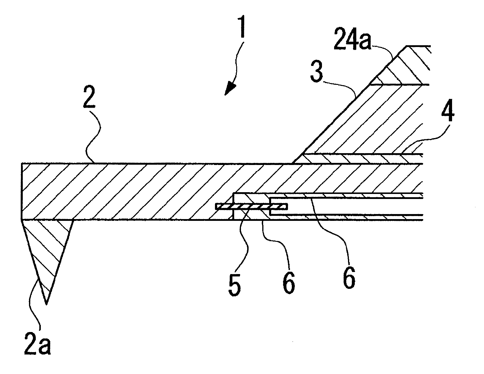
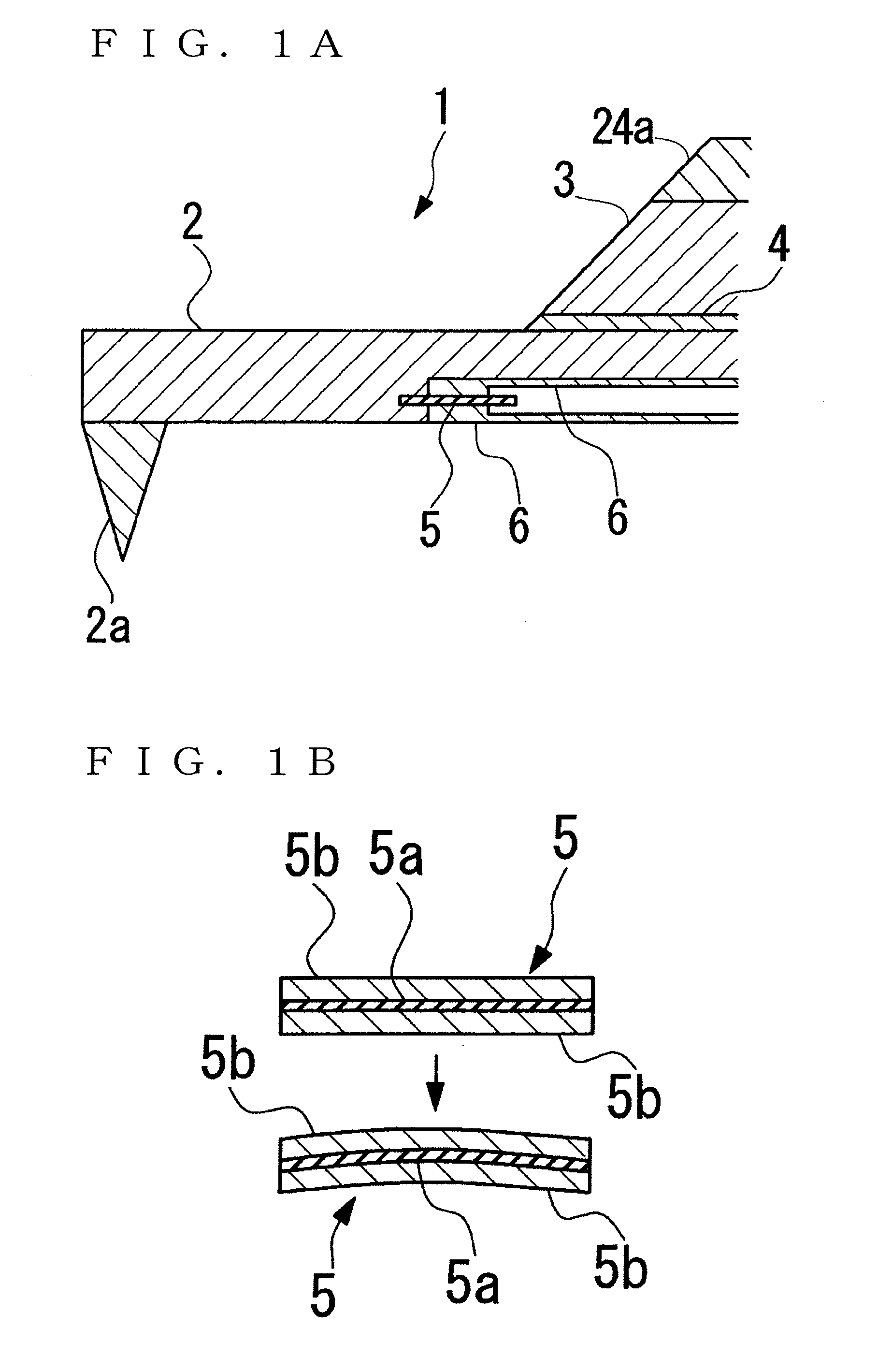
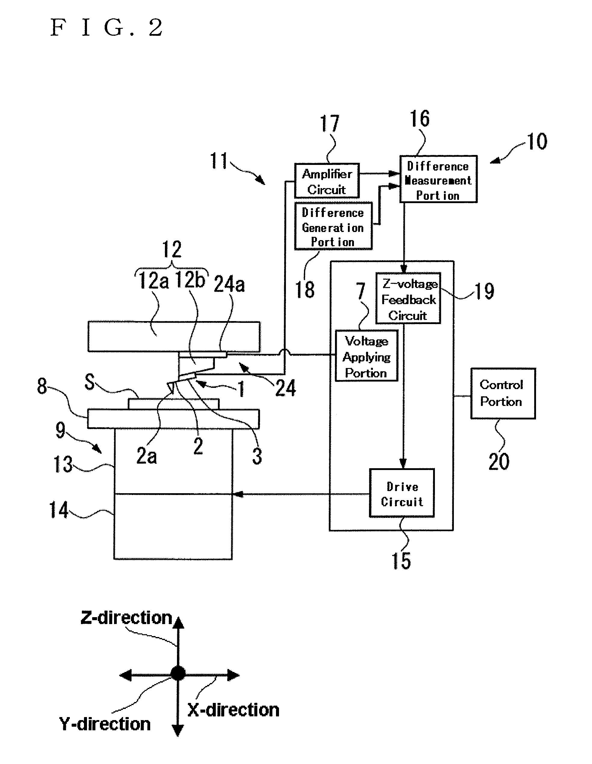
[0034]Hereinafter, a cantilever, a cantilever system, and a probe microscope according to the present invention are described with reference to FIGS. 1A and 1B and FIG. 2. The scale of each of the drawings used for the following description is adjusted as appropriate if necessary in order to obtain recognizable sizes of respective members.

[0035]As illustrated in FIGS. 1A and 1B, a cantilever 1 according to the first embodiment includes a lever portion 2 having a leaf spring characteristic, a main body portion 3 for supporting the lever portion 2 on a base end side of the lever portion 2 in a cantilever state, a cantilever vibrating portion 24a provided in the lever portion 2 or between the lever portion 2 and the main body portion 3, for vibrating the lever portion 2, a displacement detection portion 5, and wiring portions 6. The displacement detection portion 5 is provided in the lever portion 2 or between the lever portion 2 and the main body portion 3, and includes an insulating ...

fifth embodiment

[0072]As described above, in the cantilever 51 the displacement detection portion 5 is provided such that the center thereof is located at the support end of the lever portion 2. Therefore, the force of the bent lever portion 2 most effectively acts on the displacement detection portion 5, and hence a larger variation in tunnel current may be obtained and high-sensitivity and high-resolution measurement may be realized.

[0073]A difference between the sixth embodiment and the first embodiment is as follows. In the first embodiment, the main body portion 3 is provided with the single lever portion 2 and the single displacement detection portion 5 formed in the single lever portion 2. In contrast to this, in a cantilever 61 according to the sixth embodiment, as illustrated in FIG. 7, a reference portion 65 having the same structure as the displacement detection portion 5 is provided close to the lever portion 2. That is, in the sixth embodiment, a reference protruding portion 62 which ...

sixth embodiment

[0074]In the sixth embodiment, the conductor electrode portions 5b of the displacement detection portion 5 and the conductor electrode portions 5b of the reference portion 65 are connected to a Wheatstone bridge circuit 67 instead of the amplifier circuit 17.

[0075]The Wheatstone bridge circuit 67 compares tunnel currents flowing through the displacement detection portion 5 and the reference portion 65 with each other to calculate a difference therebetween, amplifies an output signal corresponding to a current value of the calculated difference, and then the amplified output signal to the difference measurement portion 16. In other words, the displacement detection mechanism 10 in this case measures the amount of the displacement of the vibration state of the lever portion 2 based on the variation in differential tunnel current.

[0076]In the displacement detection portion 5, the tunnel current is varied even by, for example, a change in temperature, in addition to the displacement of ...


PUM


Abstract

A displacement detection portion is provided in a lever portion of a cantilever or between the lever portion and a main body portion. The displacement detection portion is provided by laminating two conductor electrodes to sandwich an insulating portion. A thickness of the insulating portion (electrode interval) is set to a value capable of detecting a variation in tunnel current due to a change in electrode interval which corresponds to a displacement of the lever portion while a predetermined voltage is applied. When the lever portion is slightly displaced, the interval between the conductor electrodes changes. Therefore, the displacement may be detected as the variation in tunnel current at high resolution with sensitivity of an exponential multiple of the change in interval.

Description

RELATED APPLICATIONS[0001]This application claims priority under 35 U.S.C. §119 to Japanese Patent Application No. JP2008-218863 filed on Aug. 27, 2008, the entire content of which is hereby incorporated by reference.BACKGROUND OF THE INVENTION[0002]1. Field of the Invention[0003]The present invention relates to a self-displacement detection type cantilever having high sensitivity and high resolution, a cantilever system using the cantilever, a probe microscope including the cantilever system, and an adsorption mass sensor including the cantilever system.[0004]2. Description of the Related Art[0005]In recent years, owing to progress in nanotechnology using a semiconductor process, cantilevers having leaf spring characteristics are used in various devices and sensors to conduct various measurements for shape observation, mass, viscoelasticity, magnetic force, and the like. For example, a scanning probe microscope (SPM) includes a cantilever supported in a cantilever state. A surface ...

Claims


Application Information

Patent Timeline
IPC IPC(8): G01N13/10
CPCG01Q20/04B82Y35/00
Inventor SHIGENO, MASATSUGU
Owner HITACHI HIGH TECH SCI CORP
Why Eureka
Try Eureka