Transmission line microwave apparatus including at least one non-reciprocal transmission line part between two parts

a technology of microwave apparatus and transmission line, which is applied in the direction of waveguides, electrical devices, antennas, etc., can solve the problems of increasing the scale of the apparatus according to the resonant, and no application to the antenna apparatus that employs the non-reciprocal left-handed transmission line circui

Active Publication Date: 2010-03-11
JAPAN SCI & TECH CORP
View PDF4 Cites 38 Cited by
  • Summary
  • Abstract
  • Description
  • Claims
  • Application Information

AI Technical Summary

Benefits of technology

[0021]The second object of the present invention is to solve the above problems and provide a transmission line antenna apparatus, which forms a main beam by using a leaky wave from a transmission line such as a left-handed or right-handed transmission line and is able to control the main beam direction.

Problems solved by technology

However, no application to the antenna apparatus that employs the nonreciprocal left-handed transmission line circuit has been reported.
In particular, a resonant frequency in conventional microwave resonators is determined depending on the line length, and the microwave circuit employing the resonators, and the resonators themselves therefore have led to a problem that the apparatus configuration is increased in scale depending on the resonant frequency.

Method used


Image

  • Transmission line microwave apparatus including at least one non-reciprocal transmission line part between two parts
  • Transmission line microwave apparatus including at least one non-reciprocal transmission line part between two parts
  • Transmission line microwave apparatus including at least one non-reciprocal transmission line part between two parts

Examples


first preferred embodiment

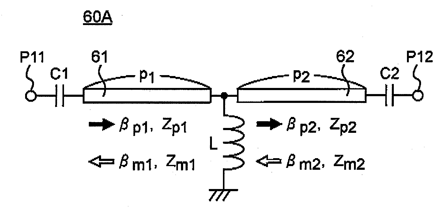
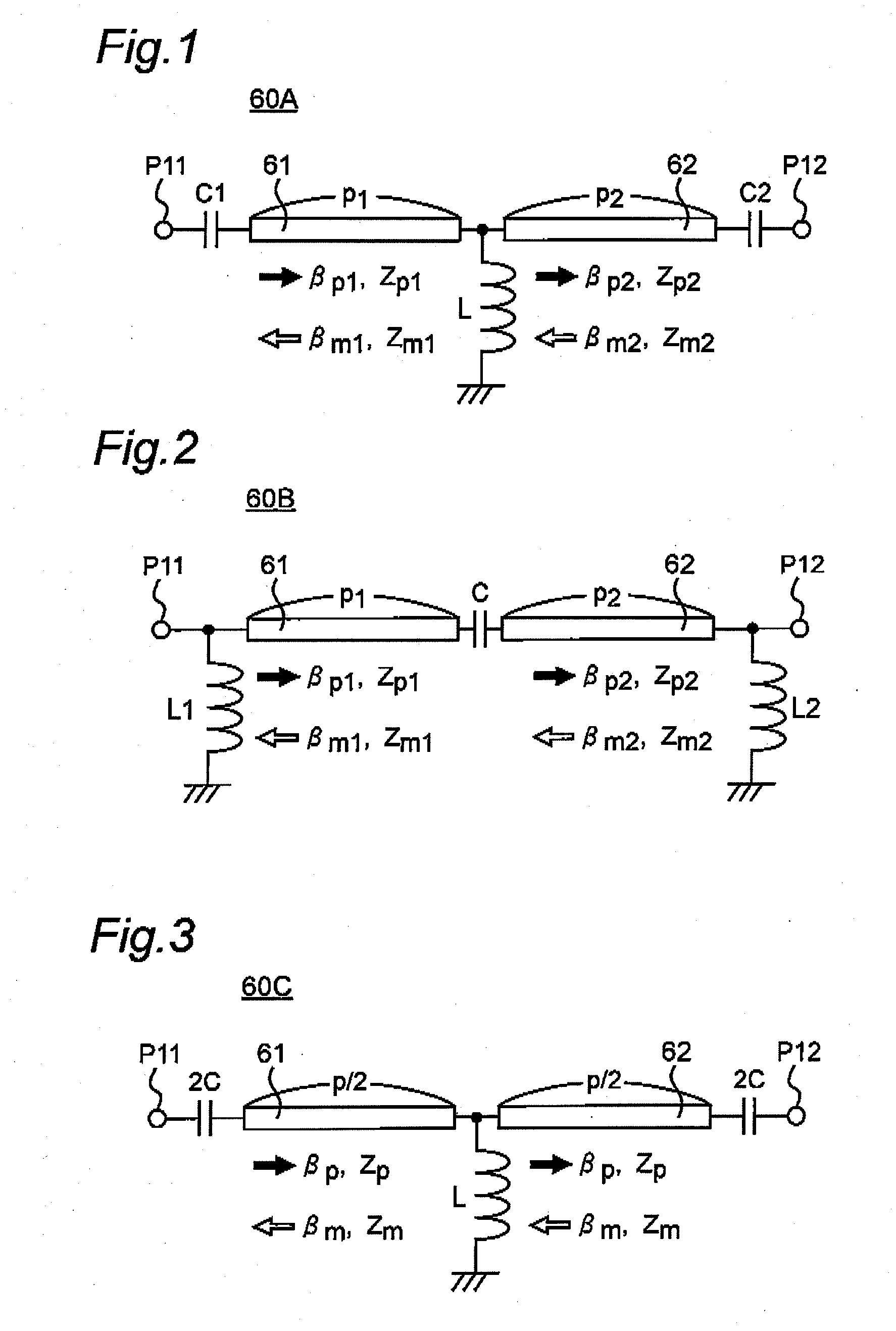
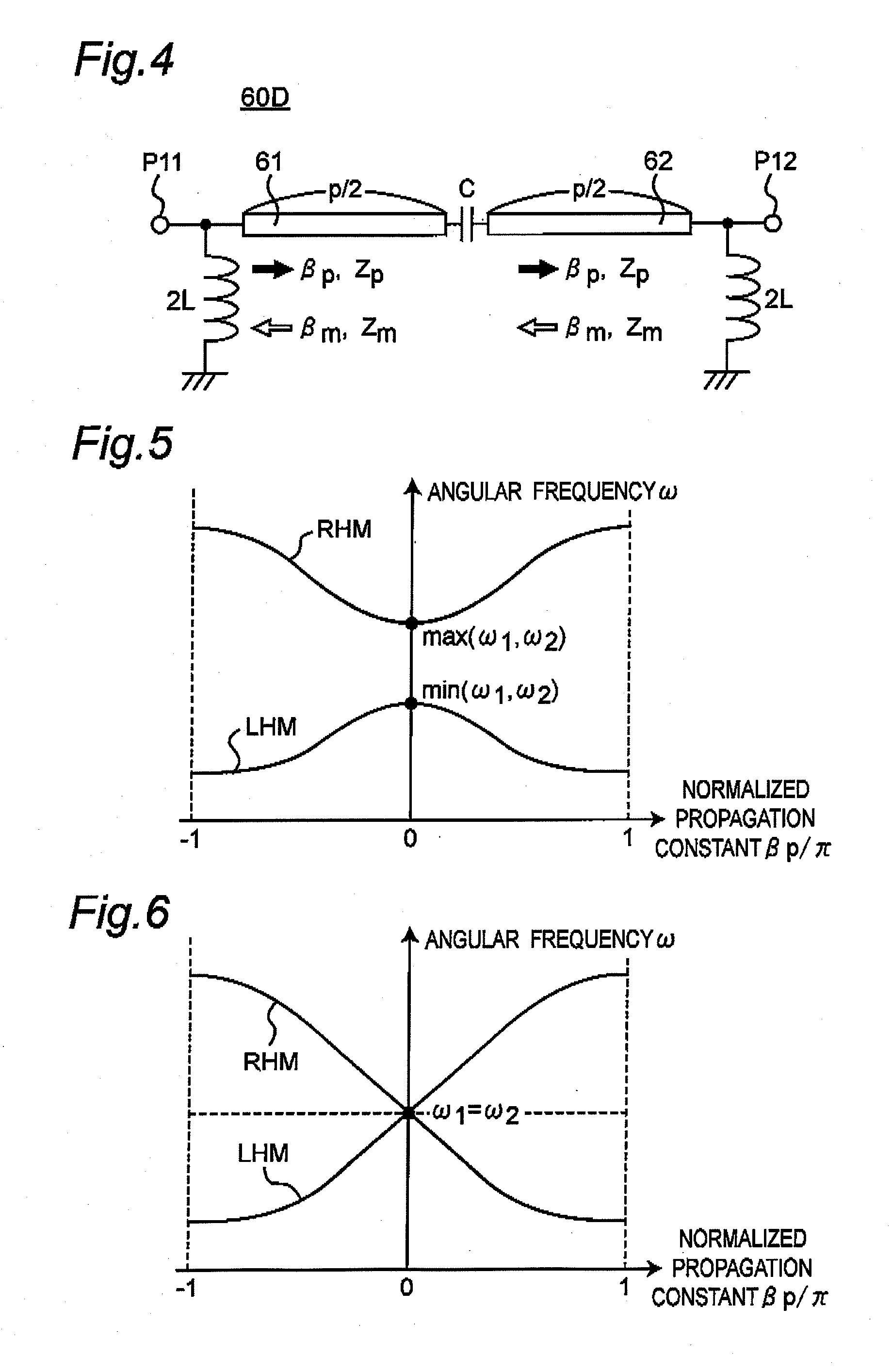
[0169]FIG. 1 is a circuit diagram showing a configuration of a unit cell 60A of a first example of a ladder-type nonreciprocal right / left handed transmission line according to the first preferred embodiment of the present invention. FIG. 2 is a circuit diagram showing a configuration of a unit cell 60B of a second example of the ladder-type nonreciprocal right / left handed transmission line of the first preferred embodiment of the present invention. FIG. 3 is a circuit diagram showing a configuration of a unit cell 60C of a third example of the ladder-type nonreciprocal right / left handed transmission line of the first preferred embodiment of the present invention. FIG. 4 is a circuit diagram showing a configuration of a unit cell 60D of a fourth example of the ladder-type nonreciprocal right / left handed transmission line of the first preferred embodiment of the present invention.

[0170]The fundamental configuration of the nonreciprocal transmission line of the present invention is fir...

second preferred embodiment

[0275]FIG. 21 is a perspective view showing the external appearance of a nonreciprocal right / left handed transmission line constituted by a rectangular waveguide 71 according to the second preferred embodiment of the present invention. FIG. 22 is a perspective view showing the internal structure (when the rectangular waveguide 71 is removed) of the nonreciprocal right / left handed transmission line of FIG. 21.

[0276]FIGS. 21 and 22 show a transmission line that utilizes the waveguide mode stuffed with ferrite magnetized in the transverse direction having an asymmetric configuration as a transmission line that has a nonreciprocal phase shift phenomenon constituting the unit cell. In this case, an asymmetric rectangular waveguide is constituted of the rectangular waveguide 71 and metal parts 73, and so forth. The effective permeability in the TE mode of the electromagnetic wave propagating in the line structure also plays the role of a capacitive element inserted in the series branch ci...

third preferred embodiment

[0277]FIG. 23 is a perspective view showing the external appearance of a non-reciprocal right / left handed transmission line constituted by a rectangular waveguide 71 according to a third preferred embodiment of the present invention. FIG. 24 is a perspective view showing the internal structure (when the rectangular waveguide 71 is removed) of the nonreciprocal right / left handed transmission line of FIG. 23.

[0278]In FIGS. 23 and 24 is shown a transmission line that utilizes an asymmetric waveguide mode of a configuration stuffed with an artificial medium constituted of magnetic metal fine wire structure parts 72a that have undergone magnetization Ms in the Y direction and metal parts 73 as a transmission line that has a nonreciprocal phase shift phenomenon constituting the unit cell. In this case, the effective permeability of the line structure also plays the role of a capacitive element inserted in the series branch circuit in the transmission line model since it becomes negative i...


PUM


Abstract

A transmission line microwave apparatus includes at least one nonreciprocal transmission line part, which includes a series branch circuit equivalently including a capacitive element and a shunt branch circuit equivalently including an inductive element. The nonreciprocal transmission line part has gyrotropic characteristic by being magnetized in a magnetization direction different from the propagation direction of a microwave, and has an asymmetric structure to a plane formed by the propagation direction and the magnetization direction. The nonreciprocal transmission line part has a propagation constant and an operating frequency set in a dispersion curve that represents a relation between the propagation constant and the operating frequency so that the propagation constant in the forward direction and the propagation constant in the backward direction have nonreciprocal phase characteristics different from each other. A microwave transmission line is constituted by cascade-connecting at least one non-reciprocal transmission line part between first and second ports.

Description

TECHNICAL FIELD[0001]The present invention relates to a transmission-line microwave apparatus provided with a transmission-line microwave circuit employing a nonreciprocal transmission line that has a nonreciprocal phase characteristic such that a propagation constant in a forward direction and a propagation constant in a backward direction are different from each other, and to a novel transmission-line antenna apparatus that uses a leaky wave from the nonreciprocal transmission line. It is noted that the microwave in the present specification refers to, for example, microwave, millimeter wave, sub-millimeter wave and terahertz wave in a frequency band higher than the UHF (Ultra High Frequency) band. A “nonreciprocal right-handed and left-handed transmission line” is hereinafter referred to as a “nonreciprocal right / left handed transmission line”.BACKGROUND ART[0002]Recently, researches on the left-handed transmission (Left Handed Transmission (LHT)) line in which the inductance and...

Claims


Application Information

Patent Timeline
Patent Type & Authority Applications(United States)
IPC IPC(8): H01P3/08
CPCH01P1/203H01P1/207H01Q13/206H01Q1/38H01P1/32
Inventor UEDA, TETSUYA
Owner JAPAN SCI & TECH CORP
Why Eureka
Try Eureka