

Omnidirectional antenna
- Summary
- Abstract
- Description
- Claims
- Application Information
AI Technical Summary
Benefits of technology
Problems solved by technology
Method used
Image

Examples
Embodiment Construction
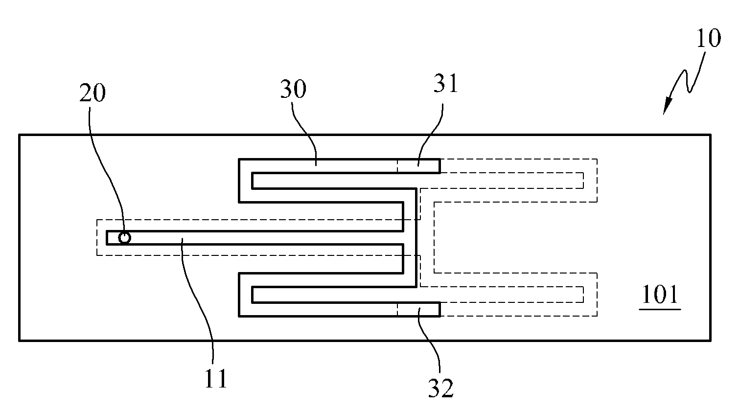
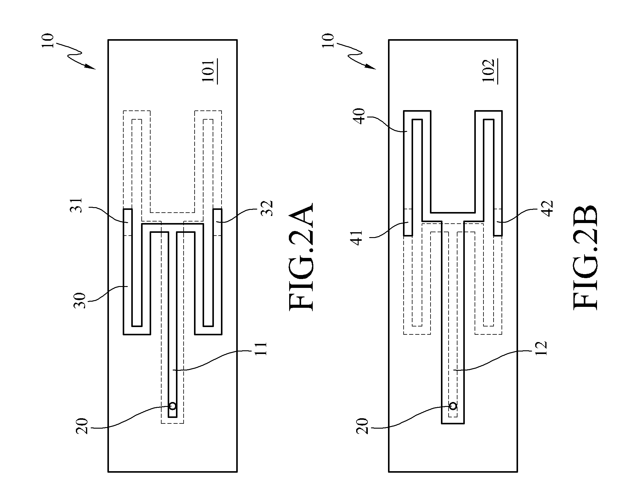
[0033]FIGS. 2A and 2B are schematic views according to a first embodiment of the present invention. FIG. 2A is a schematic view of a first surface according to the first embodiment of the present invention, and FIG. 2B is a schematic view of a second surface according to the first embodiment of the present invention. As shown in FIGS. 2A and 2B, the omnidirectional antenna includes a substrate 10, a signal feed-in portion 20, a first radiation unit 30, and a second radiation unit 40.
[0034]The substrate 10 has a first surface 101 and a second surface 102. The first surface 101 has a first circuit 11 thereon, and the second surface 102 has a second circuit 12 thereon.
[0035]The second circuit 12 overlaps the first circuit 11, but is wider than the first circuit 11. The first circuit 11 has a circuit impedance matching the circuit impedance of the first radiation unit 30. The second circuit 12 has a circuit impedance matching the circuit impedance of the second radiation unit 40. The fi...
PUM
 Abstract
Description
Claims
Application Information