Magnetic head device and magnetic disk drive apparatus with the magnetic head device

a magnetic head device and magnetic head technology, applied in the field of magnetic head devices and magnetic disk drives with magnetic head devices, can solve the problem of limited minimum bit length, and achieve the effect of greatly reducing the thickness of the mr read head element and extremely easy manufacturing of the magnetic head devi

Inactive Publication Date: 2010-03-11
TDK CORPARATION
View PDF11 Cites 3 Cited by
  • Summary
  • Abstract
  • Description
  • Claims
  • Application Information

AI Technical Summary

Benefits of technology

[0012]It is therefore an object of the present invention to provide a magnetic head device with an MR read head element and a magnetic disk drive apparatus with the magnetic head device, whereby manufacturing of the magnetic head device is extremely easy and a thickness of the MR read head element can be greatly reduced.

Problems solved by technology

However, since each free layer is very susceptible to the neighboring bits of the recorded medium when the bit length decreases less than the thickness of the free layer, the minimum bit length will be limited to the thickness of the free layer.

Method used


Image

  • Magnetic head device and magnetic disk drive apparatus with the magnetic head device
  • Magnetic head device and magnetic disk drive apparatus with the magnetic head device
  • Magnetic head device and magnetic disk drive apparatus with the magnetic head device

Examples


Embodiment Construction

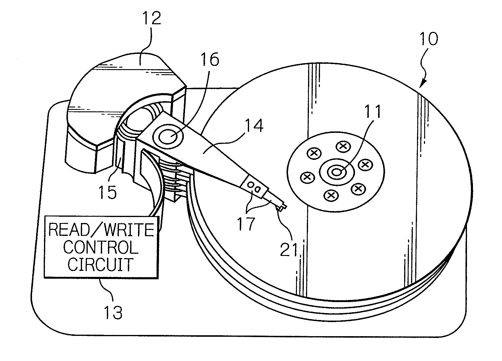
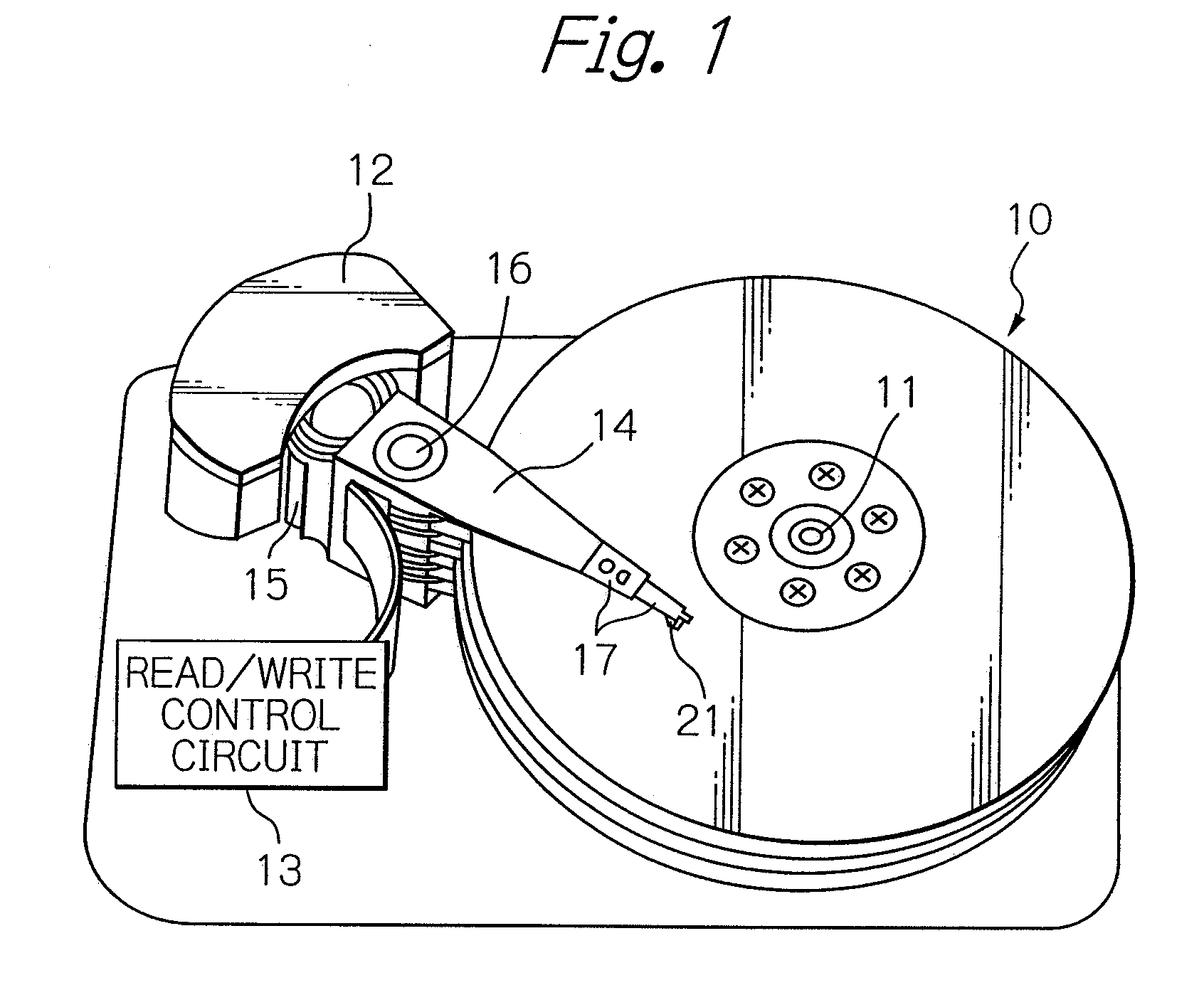
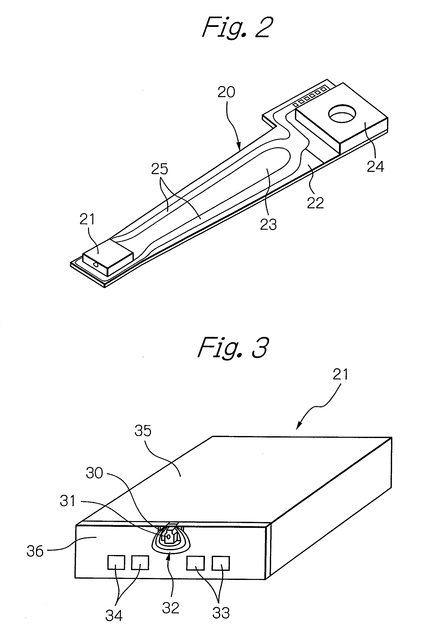
[0034]FIG. 1 schematically illustrates the main structure of a magnetic disk drive apparatus in an embodiment of the present invention, FIG. 2 illustrates an example of the structure of an HGA of FIG. 1, and FIG. 3 illustrates the composite thin-film magnetic head mounted at the end of the HGA of FIG. 2.

[0035]In FIG. 1, a reference numeral 10 denotes a plurality of magnetic disks that rotate about a rotary axis of a spindle motor 11, 12 denotes an assembly carriage device for positioning the thin-film magnetic heads or magnetic head sliders on the track, and 13 denotes a read / write control circuit for controlling the read / write operation of the thin-film magnetic heads, respectively.

[0036]The assembly carriage device 12 includes a plurality of drive arms 14. The drive arms 14 are swingable about a pivot-bearing axis 16 by a voice coil motor (VCM) 15, and are stacked in a direction along this axis 16. Each of the drive arms 14 has an HGA 17 mounted at the end thereof. The HGA 17 incl...


PUM

PropertyMeasurementUnit
thicknessaaaaaaaaaa
thicknessaaaaaaaaaa
thicknessaaaaaaaaaa

Abstract

A magnetic head device includes a magnetic head section having a first free layer with a magnetization orientation that is not previously defined but changes depending upon only external magnetic field applied, a second free layer with a magnetization orientation that is not previously defined but changes depending upon only external magnetic field applied, a nonmagnetic intermediate layer sandwiched between the first free layer and the second free layer, a first electrode layer stacked on a surface of the first free layer opposite to the nonmagnetic intermediate layer, and a second electrode layer stacked on a surface of the second free layer opposite to the nonmagnetic intermediate layer; a sense-current supply means for flowing a sense current across the first electrode layer and the second electrode layer of the magnetic head section; and a frequency divider circuit for dividing by two a frequency of an output signal produced across the first electrode layer and the second electrode layer of the magnetic head section.

Description

BACKGROUND OF THE INVENTION[0001]1. Field of the Invention[0002]The present invention relates to a magnetic head device with a magnetoresistive effect (MR) read head element, and to a magnetic disk drive apparatus with the magnetic head device.[0003]2. Description of the Related Art[0004]Recently, in order to satisfy the demand for larger recording capacity and downsizing in a magnetic disk drive apparatus, higher sensitivity and resolution of a magnetic head are required. Thus, as for a thin-film magnetic head with a recording density performance of 100 Gbspi or more, a tunnel magnetoresistive effect (TMR) head with a TMR read head element having a current perpendicular to plane (CPP) structure capable of achieving higher sensitivity and resolution is coming into practical use instead of a general giant magnetoresistive effect (GMR) head with a GMR read head element having a current in plane (CIP) structure.[0005]The head structure in which a sense current flows in a direction para...

Claims


Application Information

Patent Timeline
Patent Type & Authority Applications(United States)
IPC IPC(8): G11B5/127
CPCB82Y10/00B82Y25/00G11B5/398G11B5/3903G11B5/3909G01R33/098
Inventor OHTA, NAOKIHIRATA, KEI
Owner TDK CORPARATION
Why Eureka
Try Eureka