
Timing Phase Detection Using a Matched Filter Set

a filter set and timing technology, applied in the field of system and method processing information, can solve the problems of affecting any ability to determine, affecting the proper phase affecting the accuracy of the sample clock, so as to reduce the latency in determining

Active Publication Date: 2010-03-11
AVAGO TECH INT SALES PTE LTD
View PDF6 Cites 38 Cited by
  • Summary
  • Abstract
  • Description
  • Claims
  • Application Information

AI Technical Summary

Benefits of technology

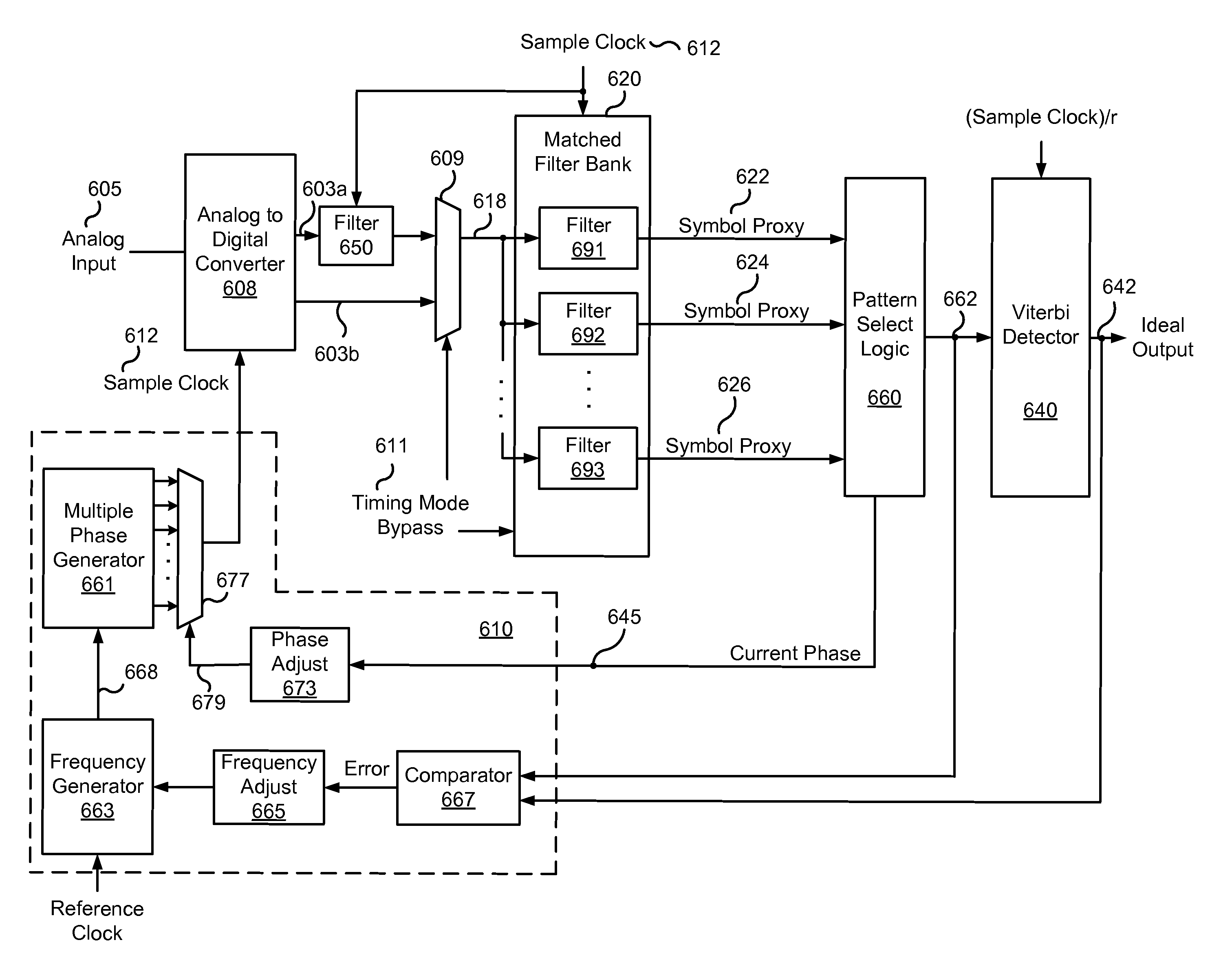
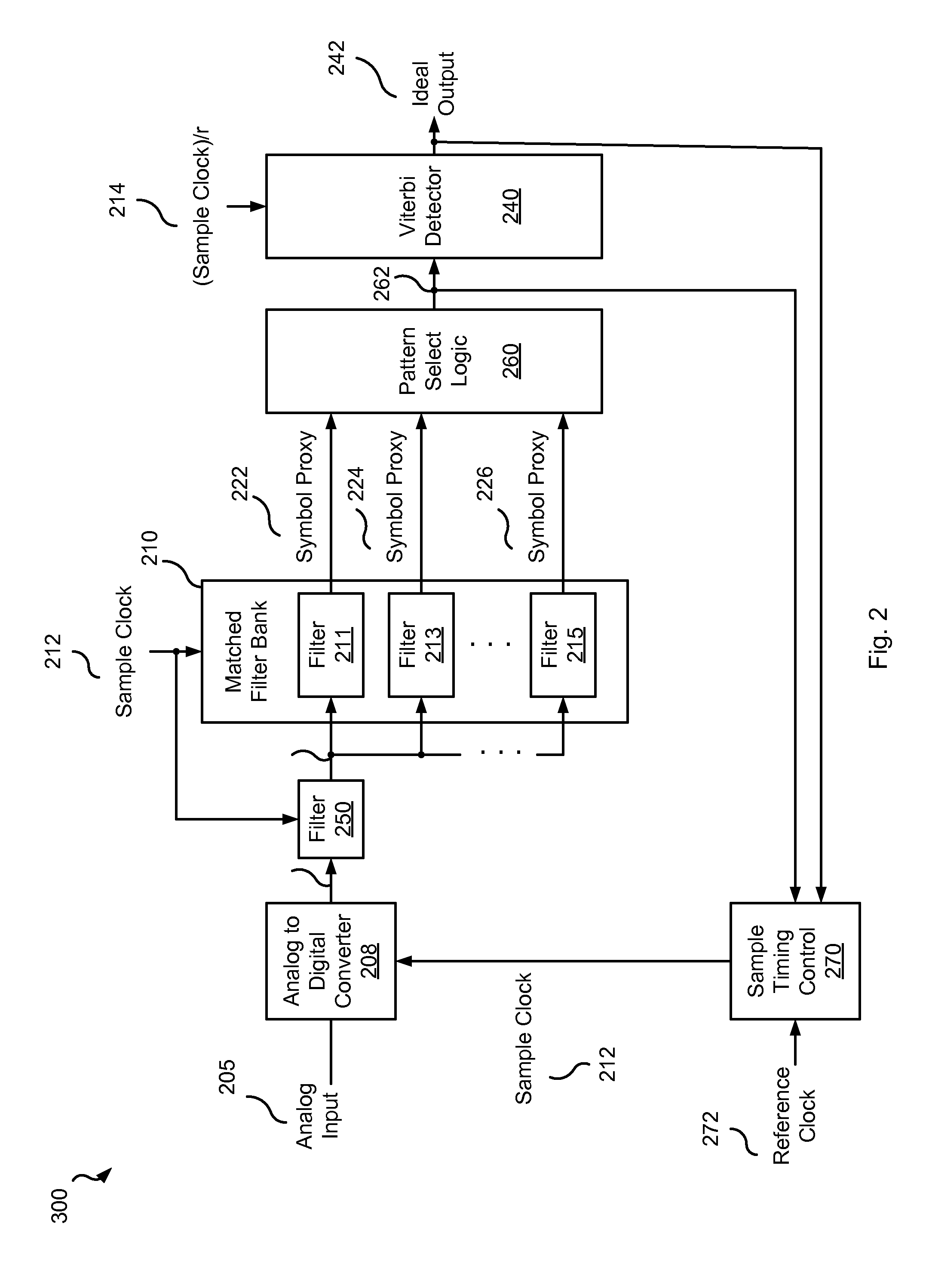
The present invention provides systems and methods for reducing latency in determining a sampling clock used for data processing. The invention includes a bank of matched filters with two or more filters tuned to detect patterns corresponding to a timing pattern sampled using different phases of a sample clock. A logic circuit is operable to determine which phase the sample clock is closer to based on the output of the matched filters. The invention also includes methods for using the data decoding circuitry to determine clock phase and communication systems with an analog to digital converter, a bank of matched filters, and a logic circuit. The technical effects of the invention include reducing latency in data processing and improving the accuracy of data transfer.

Problems solved by technology

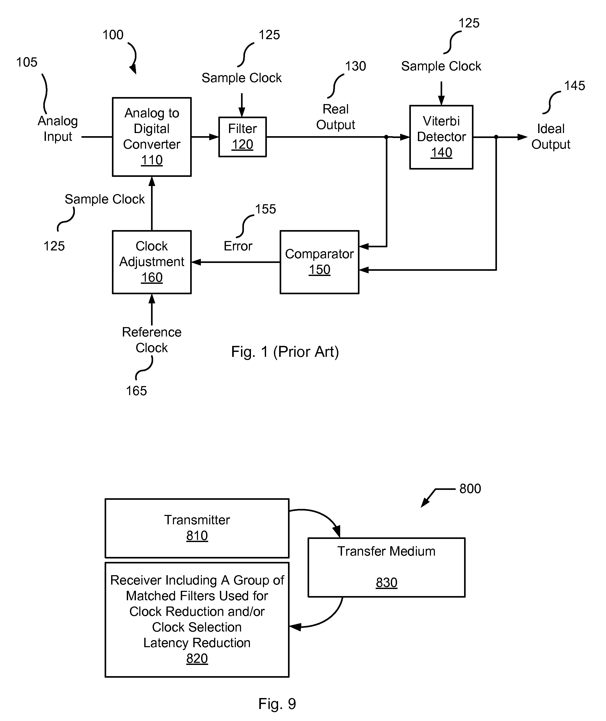
Thus, there is a substantial latency involved in determining the proper phase of sample clock 125.
Such latency negatively impacts any ability to determine the appropriate frequency of sample clock 125.
The required calculations are often, however, very complex and prone to error since there can be a significant amount of noise present in the system.

Method used


Image

  • Timing Phase Detection Using a Matched Filter Set
  • Timing Phase Detection Using a Matched Filter Set
  • Timing Phase Detection Using a Matched Filter Set

Examples


Embodiment Construction

[0024]The present invention is related to systems and methods for processing information, and more particularly to systems and methods for reducing latency in determining a sampling clock used for data processing.

[0025]Some embodiments of the present invention provide a bank of auto-convolution filters (i.e., matched filters) that feed a detector. The bank of auto-convolution filters make decisions based on short patterns within a sequence of bits, with identification of the short patterns being passed on to the detector for additional processing. Since only relatively short patterns are detected using the bank of auto-convolution filters, the number of auto-convolution filters included in the bank of auto-convolution filters remains reasonable. The value of the detector is still realized as it still calculates the difference metric on a longer sequence of bits, but its operation can be achieved at a reduced processing frequency by modifying the algorithm to operate on symbol proxie...


PUM


Abstract

Various embodiments of the present invention provide systems and methods for phase identification in data processing systems. As one example, a circuit is disclosed that includes a bank of matched filters with two or more matched filters tuned to detect patterns corresponding to a timing pattern sampled using different phases of a sample clock. In particular, the bank of matched filters includes at least a first matched filter tuned to detect a first pattern corresponding to the timing pattern sampled using a first phase of a sample clock, and a second matched filter tuned to detect a second pattern corresponding to the timing pattern sampled using a second phase of the sample clock. The circuits further include a logic circuit operable to determine whether the sample clock is closer to the first phase or the second phase based on an output of the first matched filter and an output of the second matched filter.

Description

BACKGROUND OF THE INVENTION[0001]The present invention is related to systems and methods for processing information, and more particularly to systems and methods for reducing latency in determining a sampling clock used for data processing.[0002]Data transfer systems typically include a receiver that converts an analog input into a stream of digital samples representing the analog input. For example, in a hard disk drive system, digital information is converted to an analog signal that is stored as a magnetic signal on a storage medium. The magnetic information is later sensed and converted back to an analog signal using a read circuit. The received analog signal is converted back to digital information representing the digital information originally provided to the storage medium. As another example, a wireless communication system involves a transmitter that receives digital information, and converts it to an analog signal that is transmitted. The analog signal is received and con...

Claims


Application Information

Patent Timeline
Patent Type & Authority Applications(United States)
IPC IPC(8): H04L27/06H04L27/00H04L7/00G01R25/00
CPCH04L1/0054H04L25/03248H04L7/0054
Inventor NOELDNER, DAVID
Owner AVAGO TECH INT SALES PTE LTD
Learn More