Check patentability & draft patents in minutes with Patsnap Eureka AI!

Phase/frequency detector for a phase-locked loop that samples on both rising and falling edges of a reference signal

a phase/frequency detector and reference signal technology, applied in the direction of phase difference detection, oscillation comparator circuit, pulse automatic control, etc., can solve the problems of limiting the range of the loop bandwidth of the pll, limiting the achievable noise and static phase offset performance,

Inactive Publication Date: 2010-03-11
NXP USA INC
View PDF7 Cites 9 Cited by
  • Summary
  • Abstract
  • Description
  • Claims
  • Application Information

AI Technical Summary

Problems solved by technology

However, loop bandwidth of the PLL is limited by the reference frequency.
However, in many systems the reference frequency is fixed and cannot be increased, limiting achievable noise and static phase offset performance.

Method used


Image

  • Phase/frequency detector for a phase-locked loop that samples on both rising and falling edges of a reference signal
  • Phase/frequency detector for a phase-locked loop that samples on both rising and falling edges of a reference signal
  • Phase/frequency detector for a phase-locked loop that samples on both rising and falling edges of a reference signal

Examples


Embodiment Construction

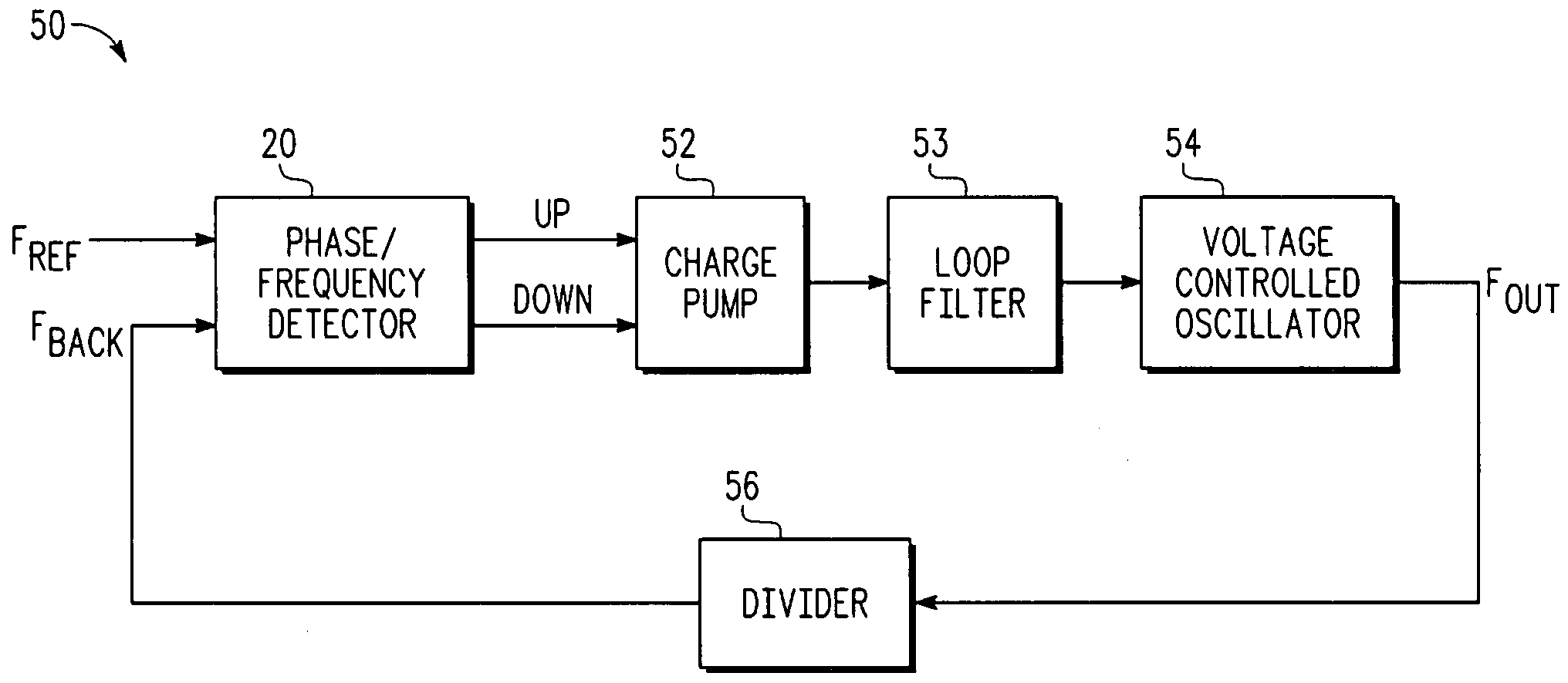
[0014]Generally, there is provided, a phase / frequency detector for use in a phase-locked loop (PLL). The phase / frequency detector effectively doubles the reference frequency by using both rising and falling edges of the reference clock while also preventing a phase ambiguity that can result in a false lock (180 degree phase ambiguity). In one embodiment, the phase-frequency detector comprises elements of two detectors operating in parallel. One set of flip-flops is triggered on the rising edges of the reference clock, and the other set of flips-flops is triggered at the time of the falling edges. The operation of the two detectors is coordinated by making one detector the “master” and the other detector the “slave”. While in phase lock, the two detectors operate independently and are prevented from interacting. This is accomplished by resetting both detectors whenever either detector issues a clear, or reset, signal. That is, a clear signal is issued whenever either UP or DOWN signa...


PUM


Abstract

A circuit comprises a first phase detector, a second phase detector, and combinational logic. The first phase detector is for detecting a phase difference between a rising edge of a first clock signal and a rising edge of a second clock signal, and for providing a first difference signal indicating the phase difference. The second phase detector is for detecting a phase difference at a time of a falling edge of the first clock signal and a time of a falling edge of the second clock signal, and for providing a second difference signal indicating the phase difference. The combinational logic is coupled to receive the first difference signal and the second difference signal, and for preventing the second difference signal from being provided when the first difference signal is being provided.

Description

BACKGROUND[0001]1. Field[0002]This disclosure relates generally to phase / frequency detectors, and more specifically, to a phase / frequency detector for a phase-locked loop (PLL) that samples on both rising and falling edges of a reference signal.[0003]2. Related Art[0004]In a PLL, a phase / frequency detector compares the phase of the reference signal to the phase of a divided voltage controlled oscillator (VCO) signal. The output of the phase detector then drives a charge pump which in turn drives a loop filter followed by a VCO. The VCO produces the VCO signal which is divided by a loop divider to generate the divided VCO signal.[0005]FIG. 1 illustrates, in partial block diagram form and partial logic diagram form, a phase / frequency detector 10 in accordance with the prior art. Phase / frequency detector 10 includes D-type flip flops 12 and 14, a delay element 18, and NAND logic gate 16. The D inputs of flip flops 12 and 14 are tied to a high logic level. One flip flop is clocked by a ...

Claims


Application Information

Patent Timeline
IPC IPC(8): H03D3/24
CPCH03D13/004H03L7/0891H03L7/089H03L7/087
Inventor MIJUSKOVIC, DEJAN
Owner NXP USA INC
Features
  • R&D
  • Intellectual Property
  • Life Sciences
  • Materials
  • Tech Scout
  • Unparalleled Data Quality
  • Higher Quality Content
  • 60% Fewer Hallucinations
Learn More